
Fractional Scaler
Programmable fractional frequency divider that divides input clock by any integer divisor (even or odd). Generates output clock with approximately 50% duty cycle at divided frequency. Supports division by 1 to 2^32-1. More flexible than even-only scaler but with slightly asymmetric duty cycle for odd divisors.
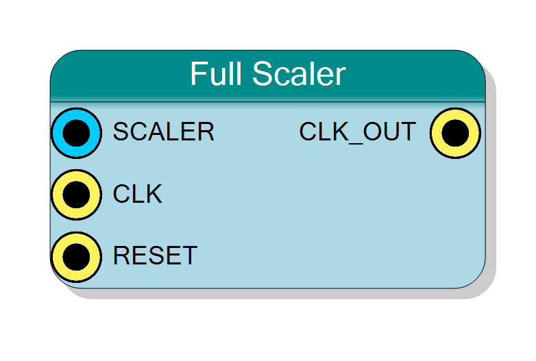
Introduction
This block implements a flexible frequency divider that supports any integer division factor (1, 2, 3, 4, 5, …), unlike the standard scaler which requires even divisors.
Key features:
- Divides by any integer: 1 to 2^32 - 1
- Supports both even and odd divisors
- Approximately 50% duty cycle (exact for even, close for odd)
- Runtime-programmable via SCALER input
- Clean, registered output
Operation:
$$ f_{\text{OUT}} = \frac{f_{\text{IN}}}{\text{SCALER}} $$
Where SCALER can be any positive integer (1, 2, 3, 4, …).
Pin Description
Division factor (any positive integer).
Type: Unsigned 32-bit integer
Valid values: 1 to 2^32 - 1 (any integer)
- SCALER=1: No division (output = input)
- SCALER=2: Divide by 2 (50% frequency)
- SCALER=N: Divide by N (1/N frequency)
Even vs Odd:
- Even: Exact 50% duty cycle
- Odd: Approximate 50% (±1 input cycle)
Dynamic change: Can be changed at runtime. New value takes effect at next counter rollover. For glitch-free change, assert RESET after changing SCALER.
Width: 32 bits (standard integer)
Input clock to be divided.
Typically system clock or external clock source.
Frequency range: DC to FPGA maximum (typically 100s of MHz)
Clocks the internal divider counter.
Default: Connects to global clock if left unconnected.
Synchronous reset (active high).
- ‘1’ = Reset: counter to 0, output to ‘0’
- ‘0’ = Normal operation
Use cases:
- Initialize to known state
- Synchronize phase
- Glitch-free SCALER change (reset before/after change)
- Align multiple scalers
Synchronous to CLK input.
Default: Connects to global reset if left unconnected.
Divided clock output.
Frequency: f_OUT = f_IN / SCALER
Duty cycle:
- Even SCALER: Exactly 50%
- Odd SCALER: ⌊SCALER/2⌋ / SCALER
Phase: Aligned to CLK_IN rising edges
Initial state: ‘0’ after reset
Properties:
- Registered output (glitch-free)
- Suitable for clock signal (even divisors best)
- Can drive logic or clock networks
- Edges synchronous to CLK_IN
Example (SCALER=7, f_IN=100MHz):
- f_OUT = 14.29 MHz
- High for 3 CLK_IN cycles (30 ns)
- Low for 4 CLK_IN cycles (40 ns)
- Period = 7 CLK_IN cycles (70 ns)
- Duty cycle = 42.9%
Properties
This component has no configurable properties.
Division factor is set at runtime via the SCALER input port.
SCALER can be connected to:
- Constant for fixed division
- Register for runtime configuration
- Control logic for dynamic selection
- Software-controllable register for flexible operation
Functional description
The fractional scaler counts input cycles and toggles output to approximate the desired division ratio:
Operation principle
- Internal counter counts from 0 to SCALER-1
- Output transitions based on counter value:
- OUT=‘1’ when counter < SCALER/2
- OUT=‘0’ when counter ≥ SCALER/2
- Counter resets to 0 when reaching SCALER-1
Duty cycle behavior
Even divisors (SCALER = 2, 4, 6, …):
- Exactly 50% duty cycle
- High time = Low time = SCALER/2 cycles
- Identical to standard Scaler
Odd divisors (SCALER = 3, 5, 7, …):
- Approximately 50% duty cycle
- High time = ⌊SCALER/2⌋ cycles
- Low time = ⌈SCALER/2⌉ cycles
- Asymmetry = 1 input cycle
Examples
SCALER = 4 (even):
- High: 2 cycles, Low: 2 cycles
- Duty cycle: 50.0%
SCALER = 5 (odd):
- High: 2 cycles, Low: 3 cycles
- Duty cycle: 40.0%
SCALER = 7 (odd):
- High: 3 cycles, Low: 4 cycles
- Duty cycle: 42.9%
SCALER = 1 (special case):
- Output = Input (no division)
- 50% duty cycle (same as input)
Frequency division table
| SCALER | Input Freq | Output Freq | High Cycles | Low Cycles | Duty Cycle |
|---|---|---|---|---|---|
| 1 | 100 MHz | 100 MHz | - | - | 50% |
| 2 | 100 MHz | 50 MHz | 1 | 1 | 50% |
| 3 | 100 MHz | 33.33 MHz | 1 | 2 | 33.3% |
| 4 | 100 MHz | 25 MHz | 2 | 2 | 50% |
| 5 | 100 MHz | 20 MHz | 2 | 3 | 40% |
| 10 | 100 MHz | 10 MHz | 5 | 5 | 50% |
| 11 | 100 MHz | 9.09 MHz | 5 | 6 | 45.5% |
| 100 | 100 MHz | 1 MHz | 50 | 50 | 50% |
Timing diagrams
Even divisor (SCALER=4)
Odd divisor (SCALER=5)
For SCALER=5 (odd):
- High for 2 cycles (counter=0,1)
- Low for 3 cycles (counter=2,3,4)
- Asymmetric but functional
Typical use cases
- Arbitrary frequency division: When exact ratio needed (even or odd)
- Baud rate generation: Standard baud rates often require odd divisors
- Video timing: Pixel clocks sometimes need odd divisors
- Flexible clock generation: When divisor varies or is odd
- Protocol clocks: When protocol requires specific odd division
- Legacy compatibility: Matching specific clock frequencies
Design considerations
When to use Fractional Scaler vs Standard Scaler
Use Fractional Scaler when:
- Need odd division factors
- Division factor varies and may be odd
- Flexibility more important than perfect duty cycle
- Target frequency requires odd divisor
Use Standard Scaler when:
- Only even division needed
- Exact 50% duty cycle required
- Simpler implementation preferred
- Output drives clock-sensitive logic
Duty cycle implications
For odd divisors, duty cycle asymmetry = 1 input cycle:
$$ \text{Asymmetry Time} = T_{\text{IN}} = \frac{1}{f_{\text{IN}}} $$
Impact:
- @ 100 MHz input: 10 ns asymmetry
- @ 10 MHz input: 100 ns asymmetry
Usually negligible for:
- Slow output frequencies (asymmetry « output period)
- Logic that’s not duty-cycle sensitive
- Sampling/counting applications
May matter for:
- High-precision timing
- Duty-cycle-sensitive circuits
- High-frequency outputs with odd divisors
Scaler value = 1
Special case: SCALER=1 means no division
- Output follows input
- Useful for runtime-selectable division
- “Bypass” mode
Frequency calculation
$$ f_{\text{OUT}} = \frac{f_{\text{IN}}}{\text{SCALER}} $$
Examples:
- 100 MHz / 3 = 33.33 MHz
- 200 MHz / 7 = 28.57 MHz
- 50 MHz / 13 = 3.846 MHz
Resource usage
Similar to standard scaler:
- Counter: ceil(log2(SCALER_max)) bits
- Comparator logic
- Output register
- Minimal additional logic