
RF Complex AGC (linear)
Automatic Gain Control for a complex I/Q stream: a single-multiplier gain stage whose gain is driven by a leaky-integrator loop that measures the OUTPUT power |y|^2 and steers it toward a programmable target. Typical use: hold a downstream detector at a constant drive level across a wide input dynamic range.
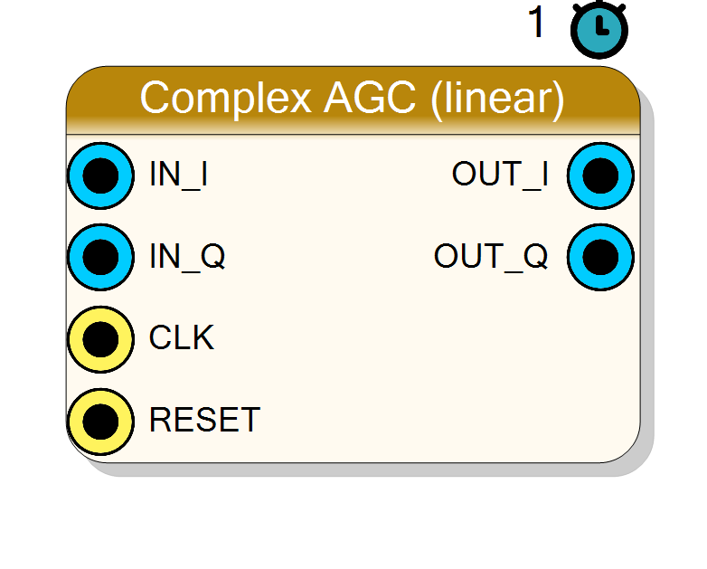
Introduction
The Complex AGC (linear) block automatically scales a complex baseband stream so its output power sits at a chosen target. It closes the loop around the output (not the input):
y = clamp( (IN * gain) >> GainFrac , OUT_MIN, OUT_MAX )
magsq = y_i^2 + y_q^2
avg += (magsq - avg) >> AvgShift (leaky IIR envelope estimate)
err = TARGET - avg (TARGET = 2^TargetLog2)
gain += err >> LoopShift (integrator)
gain = clamp(gain, MIN_GAIN, MAX_GAIN)
Because the loop measures the output, it converges to the point where the
smoothed |y|^2 equals TARGET. The output is saturating: when the
gain would push |y| past full scale the sample is clamped rather than
wrapped, and the loop naturally stops raising the gain because the measured
output power is capped by the saturation.
Pin Description
Properties
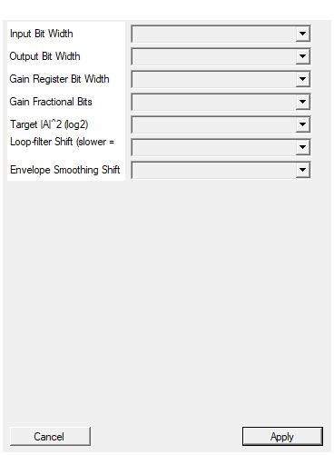
Bit width of each I/Q input (signed).
Bit width of each signed I / Q input sample. Range 4 to 32, default 16.Default: 16
Options: 4 5 6 7 8 9 10 11 12 13 14 15 16 17 18 19 20 21 22 23 24 25 26 27 28 29 30 31 32
Bit width of each I/Q output (signed). Typical: InputSize + 2.
Bit width of each signed I / Q output sample. Range 8 to 40, default 18. TypicalInputSize + 2. Output is saturated to this range.
Default: 18
Options: 8 9 10 11 12 13 14 15 16 17 18 19 20 21 22 23 24 25 26 27 28 29 30 31 32 33 34 35 36 37 38 39 40
Bit width of the internal gain (unsigned).
Bit width of the internal (unsigned) gain register. Range 12 to 24, default 18. Sets the maximum gain (MAX_GAIN = 2^GainSize - 1).
Default: 18
Options: 12 13 14 15 16 17 18 19 20 21 22 23 24
Fractional bits of the gain (gain=2^GainFrac means unity).
Number of fractional bits in the gain (gain = 2^GainFrac is unity).
Range 4 to 20, default 12. Minimum gain is 2^(GainFrac-4)
(= 1/16 unity).
Default: 12
Options: 4 5 6 7 8 9 10 11 12 13 14 15 16 17 18 19 20
Target power = 2^TargetLog2. Choose so it fits comfortably below 2^(2*InputSize+1).
Target output power as a power of two:TARGET = 2^TargetLog2. Range
8 to 40, default 26. Choose so it fits comfortably below the
output full-scale power 2^(2*OutputSize+1).
Default: 26
Options: 8 9 10 11 12 13 14 15 16 17 18 19 20 21 22 23 24 25 26 27 28 29 30 31 32 33 34 35 36 37 38 39 40
Integrator shift; larger = slower AGC. 12-20 typical.
Loop-filter (integrator) shift:gain += err >> LoopShift. Larger =
slower, more stable AGC; smaller = faster but more overshoot. Range
4 to 24, default 16. Typical 12-20.
Default: 16
Options: 4 5 6 7 8 9 10 11 12 13 14 15 16 17 18 19 20 21 22 23 24
Leaky IIR shift for the |A|^2 estimate. 4-10 typical.
Envelope-smoothing shift for the leaky-IIR|y|^2 estimate. Effective
time constant ~2^AvgShift samples. Range 0 to 16, default 6.
Typical 4-10.
Default: 6
Options: 0 1 2 3 4 5 6 7 8 9 10 11 12 13 14 15 16
Usage
Stateful / feedback behaviour
This is an IIR / stateful feedback loop. The C++ core keeps two static
registers that carry the loop state between samples:
static gain_t gain = 1<<GainFrac; // gain register, starts at unity
static avg_t avg = 0; // leaky |y|^2 estimate
gain is an unsigned Q-format value with GainFrac fractional bits, so
gain = 2^GainFrac is unity. Each clock the gain multiplies the input, the
product is right-shifted by GainFrac to remove the fractional scaling and
saturated to the output range. The output power feeds a two-pole control
path: a leaky IIR (AvgShift) smooths the instantaneous |y|^2, and an
integrator (LoopShift) walks the gain toward zero error.
The two shift / time-constant parameters
- AvgShift — envelope smoothing. The leaky IIR
avg += (magsq - avg) >> AvgShifthas an effective time constant of about2^AvgShiftsamples. Larger = smoother power estimate, but adds lag. Typical 4-10. - LoopShift — loop-filter integrator gain.
gain += err >> LoopShiftmeans a larger value takes smaller steps, giving a slower, more stable AGC. Smaller = faster attack/decay but more overshoot / ripple. Typical 12-20.
Together they set the AGC settling time and stability; think of LoopShift
as the dominant loop bandwidth control and AvgShift as anti-jitter on the
measurement.
Gain clamping
The gain register is clamped every cycle to [MIN_GAIN, MAX_GAIN], where
MIN_GAIN = 2^(GainFrac-4) (i.e. 1/16 of unity) and
MAX_GAIN = 2^GainSize - 1. This bounds the AGC’s attenuation and maximum
boost and stops the integrator winding up.
Choosing the target
TARGET = 2^TargetLog2 is compared against |y|^2. Pick TargetLog2 so
the target power sits comfortably below the output full-scale power
2^(2*OutputSize+1); too high and the loop lives permanently in output
saturation.
Bit widths
IN_I,IN_Q: signedInputSizebits.OUT_I,OUT_Q: signedOutputSizebits (saturated). TypicalOutputSize = InputSize + 2.gain: unsignedGainSizebits,GainFracfractional (unity =2^GainFrac).- internal power estimate
avg:2*OutputSize + 8bits.
Reset behaviour
RESET is the HLS synchronous reset (ap_rst). On assertion the loop state
is re-initialised: gain returns to unity (2^GainFrac) and the power
estimate avg clears to zero, so the AGC re-converges from unity gain.
Latency and throughput
#pragma HLS PIPELINE II=1: one sample pair per clock.- 1-clock sample latency (loop convergence takes many samples, set by the shift parameters).
- All ports use
ap_none. #pragma HLS INTERFACE ap_ctrl_none port=return: no block-level control.
Typical applications
- Constant-drive leveling ahead of a demodulator or detector.
- Dynamic-range compression of a fading / bursty I/Q signal.
- Front-end leveling for coherent processing that assumes a fixed scale.
Resources & Timing
-
Latency: 1 clock cycle per sample (loop settling is many samples, set by LoopShift/AvgShift)
-
Throughput: 1 sample per clock (II=1)
One gain multiplier per channel plus two squarers for the |y|^2 measure; the loop filter and IIR are add/shift only (no dividers). Stateful IIR feedback (static gain and avg registers). Output saturates rather than wraps; the gain register is clamped every cycle to bound attenuation/boost and prevent integrator wind-up.