
Sin-Cos (Cordic)
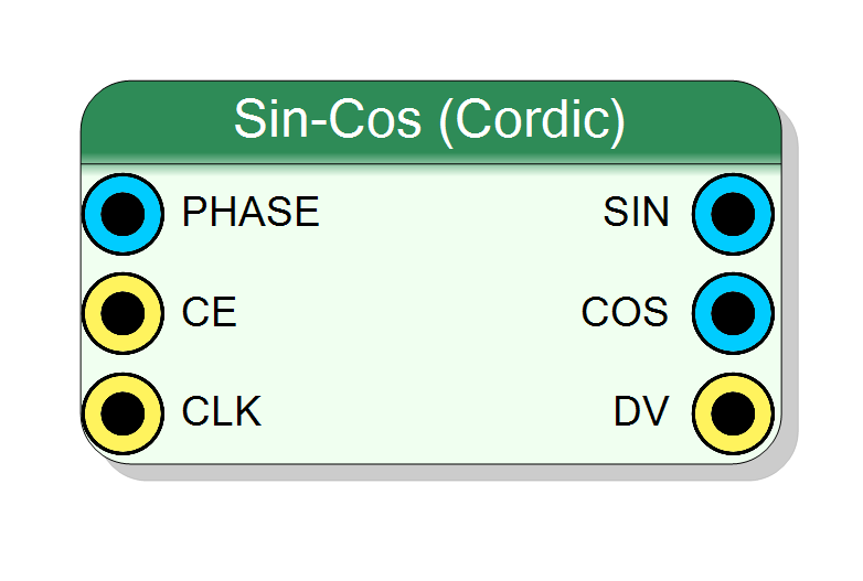
CORDIC-based sine and cosine generator built on top of the Xilinx CORDIC IP core. It accepts phase values in scaled radians or radians format, supports configurable input/output widths (16-64 bits), and produces simultaneous SIN and COS outputs with high precision.
Introduction
The block computes sine and cosine of an input phase angle using the
CORDIC (COordinate Rotation DIgital Computer) algorithm.
On every rising edge of CLK, when CE = 1, the core accepts a phase
value on PHASE and produces:
$$ \mathrm{SIN}(n) = \sin(\theta[n]), \quad \mathrm{COS}(n) = \cos(\theta[n]) $$
where $\theta[n]$ is the input phase at cycle $n$.
The phase input format can be:
- Scaled Radians: fixed-point representation in range $[-1, 1)$ corresponding to $[-\pi, \pi)$
- Radians: direct radians representation
The internal datapath is implemented with the Xilinx CORDIC IP core
configured for Sin and Cos function. The DV (Data Valid) output
indicates when new valid results are available.
Pin Description
CE = 1, the core accepts new phase input.
When CE = 0, the core ignores input and may stall the pipeline.
DV = 1.
DV = 1.
SIN and COS
outputs are available.
Properties
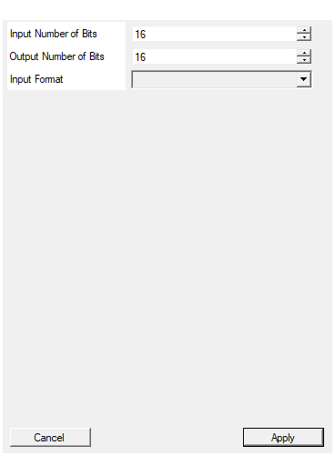
Number of bits in for phase input
Number of bits for the phase input ($N_{\text{phase}}$). Range: 16 – 64. Higher values provide finer phase resolution. Changing this value re-configures the underlying CORDIC core.Default: 16
Range: 16 – 64
Number of bits in for result
Number of bits for the SIN and COS outputs ($N_{\text{out}}$). Range: 16 – 64. Higher values provide better amplitude precision. Changing this value re-configures the underlying CORDIC core and affects latency.Default: 16
Range: 16 – 64
Select between Fixed point scaled radiants (number between -1 and 1) and radiands. The fixed point data format is 3.XXXX
Selects the input phase format:
- Scaled Radiants: Phase normalized to $[-1, 1)$ representing $[-\pi, \pi)$. Fixed-point format 3.XXX.
- Radiants: Direct radians representation.
Note: The property name uses “Radiants” in the code but refers to “Radians” (the mathematical unit).
Default: Scaled Radiants
Options: Scaled Radiants Radiants
Functional description
The component realizes the trigonometric functions:
$$ \begin{aligned} y_{\text{sin}}[n] &= \sin(\theta[n]) \ y_{\text{cos}}[n] &= \cos(\theta[n]) \end{aligned} $$
with
- $\theta[n]$ →
PHASEinput - $y_{\text{sin}}[n]$ →
SINoutput - $y_{\text{cos}}[n]$ →
COSoutput
Both input and output are in signed fixed-point format.
Input phase format
Scaled Radians (default): The input represents phase normalized to $[-1, 1)$ with fixed-point format 3.XXXX (3 integer bits, remaining fractional):
- $-1.0$ → $-\pi$ radians
- $0.0$ → $0$ radians
- $+0.999…$ → $\approx +\pi$ radians
Radians: Direct representation of angle in radians.
Output format
Both SIN and COS outputs are signed fixed-point numbers in the range
$[-1, +1)$ with format S.XXXX (1 sign bit, remaining fractional).
Mathematical background
The CORDIC algorithm computes trigonometric functions through iterative vector rotations. For the rotation mode used here:
$$ \begin{bmatrix} x_{n+1} \ y_{n+1} \end{bmatrix} = \begin{bmatrix} \cos(\theta) & -\sin(\theta) \ \sin(\theta) & \cos(\theta) \end{bmatrix} \begin{bmatrix} x_n \ y_n \end{bmatrix} $$
The number of iterations (and thus latency and accuracy) depends on the configured bit width.
Timing
The CORDIC IP has a data-dependent latency that varies with the number of bits configured. Typical latency is approximately:
$$ \text{Latency} \approx N_{\text{bits}} + \text{overhead} $$
where $N_{\text{bits}}$ is the output bit width.
The DV (Data Valid) output pulse indicates when new valid SIN and
COS outputs are available.
Typical use cases
- Direct Digital Synthesis (DDS) in SDR applications
- Digital down-converters and up-converters
- Phase-locked loops (PLL) simulation
- Signal generation for test equipment
- Complex signal processing (I/Q modulation/demodulation)
- Coordinate transformations (Cartesian ↔ Polar)
Waveform example
Conceptual timing diagram (actual latency depends on configuration):