
Peak TM
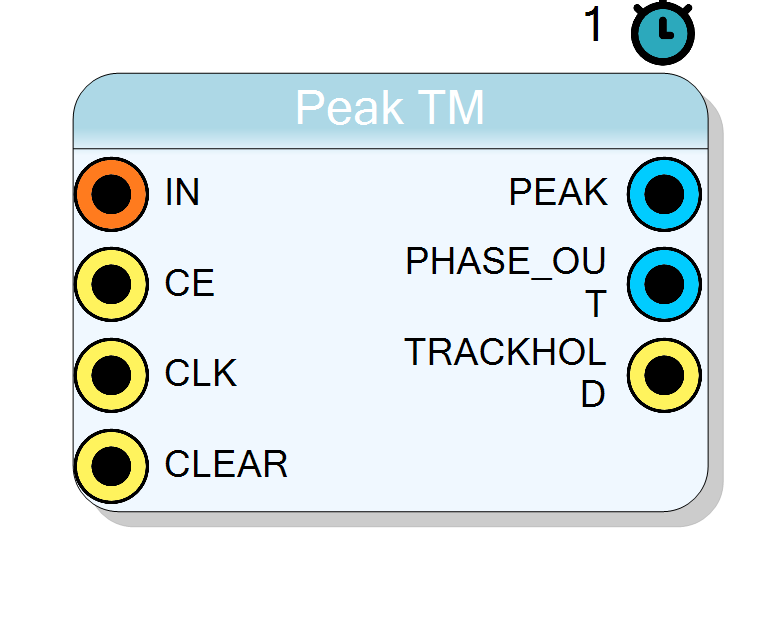
Time–multiplexed peak stretcher. At every clock edge the block receives TMFactor parallel samples (e.g. 4) and stores the highest value ever observed together with the index (phase) of the winning sample. The design is fully synchronous, single–clock, 1-cycle latency.
Introduction
The Peak TM IP identifies the maximum amplitude among N = TMFactor samples that arrive simultaneously (time-multiplexed bus).
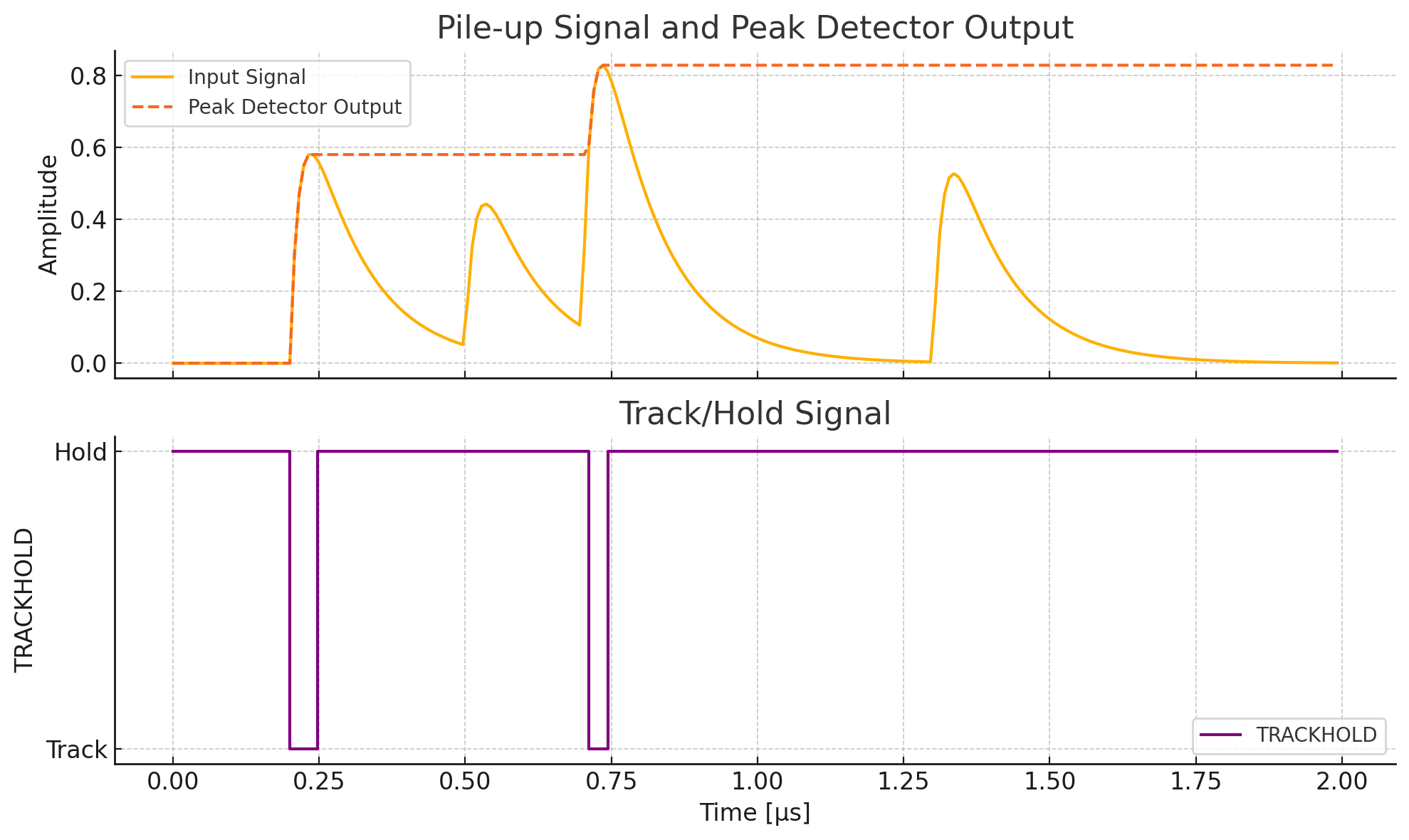
A running peak value is kept in an internal register; any new sample larger than the stored peak updates the register and resets the track/hold flag.
Pin Description
$$\text{DATAIN} = {x_{N-1},\dots,x_{1},x_{0}}$$
When
'0' the internal state is frozen and no comparison is performed.
All synchronous operations occur on its rising edge.
Clears the peak register, sets
DATA_OUT = 0, de-asserts TRACKHOLD, and zeroes PHASE_OUT.
Updated one clock cycle after a higher
DATA_IN sample is observed with CE='1'.
TMFactor bits) indicating which slice of DATA_IN produced the most recent peak.Example for TMFactor = 4:
0100 ⇒ slice 1.
0 = tracking (a new higher peak has just been stored)1 = holding (current DATA_OUT still maximal).
Properties
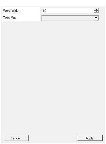
Width of the input data in bits
Bit-width of each individual sample $x_i[k]$ (range 4–32).• Affects comparator width and register size.
• Changing this property triggers IP re-generation.
Default: 16
Range: 4 – 32
Set number of samples for each clock cycle
TMFactor – number of parallel samples accepted each clock (2, 4, 8, 16, 32).• Directly sets input bus width and
PHASE_OUT size.• Resource usage grows linearly with this value.
• Must match the upstream time-demultiplexer configuration.
Default: 4
Options: 2 4 8 16 32
Functional overview
Consider the vector
$$\mathbf{x}[k] = \bigl( x_0[k],,x_1[k],,\dots,,x_{N-1}[k] \bigr)$$
sampled at clock cycle k, where $x_i[k]$ has WordWidth bits and $N=\text{TMFactor}$.
The block computes
$$x_{\max}[k] = \max_{0\le i < N} {x_i[k]}$$
and the corresponding index
$$p[k] = \operatorname*{arg,max}_{0\le i < N} {x_i[k]}.$$
The internal peak register $P[k]$ follows the recurrence
$$P[k+1] = \begin{cases}
x_{\max}[k] & \text{if } x_{\max}[k] > P[k] \
P[k] & \text{otherwise.}
\end{cases}$$
TRACKHOLD is asserted ('1') when the previously stored peak is held (no update occurred in the current cycle).
PHASE_OUT is a one-hot vector encoding $p[k]$ and is refreshed only when a new peak is stored.
Timing
- All registers are clocked on the rising edge of
CLK. - Latency: 1 clock cycle from a valid input (
CE='1') to validDATA_OUT,PHASE_OUT,TRACKHOLD.
Real-world application
In high-rate gamma spectroscopy, four ADC channels are interleaved (TM = 4) to achieve an effective 250 MSPS stream.
The Peak TM block continuously monitors these parallel outputs, reporting both the energy peak (DATA_OUT) and the ADC phase (PHASE_OUT) that yielded the event, enabling walk-correction algorithms downstream.