
RF Goertzel (single tone)
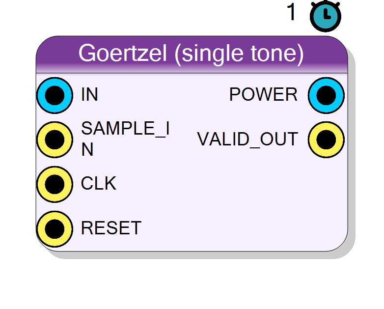
Single-frequency Goertzel tone detector. Computes the power |X(k)|^2 of ONE DFT bin over a block of N samples using a second-order IIR resonator, far cheaper than a full FFT when only one frequency must be monitored. Typical use: narrowband tone / pilot detection, DTMF, or measuring the energy at one line of the spectrum.
Introduction
The Goertzel (single tone) block evaluates a single DFT bin X(k)
and emits its power |X(k)|^2 once every N input samples. It is the
cheapest way to answer “how much energy is at frequency f?” without
computing a whole FFT.
The Goertzel algorithm is a second-order IIR resonator per bin. For a
real input x[n] it runs the recurrence
s[n] = x[n] + 2*cos(w)*s[n-1] - s[n-2]
over a block of N samples (w = 2*pi*k/N), where the single coefficient
2*cos(w) is the only per-sample multiply. After the last sample of the
block the magnitude is recovered from just the last two states:
power = s1^2 + s2^2 - 2*cos(w)*s1*s2 (s1 = s[N-1], s2 = s[N-2])
The target frequency is snapped to the nearest DFT bin
k = round(N * f / Fs)
which gives a frequency resolution (bin spacing) of Fs / N. Raising N
narrows the analysis window (better selectivity, longer integration time);
lowering it widens the bin and shortens latency.
For a per-sample (sliding) output see Component_GoertzelSliding; to monitor several tones with one shared multiplier see Component_GoertzelMulti.
Pin Description
|X(k)|^2, updated once per N-sample block and held between
updates. Signed bus, 2(InputSize + ceil(log2 N) + 2) + 4* bits
(POW_SIZE); the value itself is non-negative.
Properties
Real: one input channel. Complex: I/Q input (full complex DFT bin).
Real: single input channelIN (folds the negative-frequency
image; use 0 < f < Fs/2). Complex: I/Q input IN_I / IN_Q
for a true one-sided complex DFT bin. Default Real.
Default: Real
Options: Real Complex
Bit width of the input sample(s) (signed).
Bit width of each signed input sample. Range 4..32, default 16. Sets the internal state and POWER widths.Default: 16
Options: 4 5 6 7 8 9 10 11 12 13 14 15 16 17 18 19 20 21 22 23 24 25 26 27 28 29 30 31 32
Bit width of the cos/sin coefficients (signed).
Bit width of the signedcos/sin coefficients (scale
2^(CoefSize-2)). One of 12, 14, 16, 18, 20, 24. Larger values lower
coefficient-quantisation error at the cost of DSP width. Default
18.
Default: 18
Options: 12 14 16 18 20 24
Goertzel block length: DFT size. Frequency resolution = Fs/N, latency = N samples.
Goertzel block length = DFT size N. Frequency resolution isFs/N
and the measurement latency is N samples. One of
16, 32, 48, 64, 96, 128, 192, 256, 384, 512, 768, 1024, 2048, 4096,
8192. Default 256.
Default: 256
Options: 16 32 48 64 96 128 192 256 384 512 768 1024 2048 4096 8192
Sample rate of the data feeding this block (after any decimation). Used to map the target frequency to a DFT bin.
Sample rate (Hz) of the data feeding this block, after any upstream decimation. Used to map the target frequency to a DFT bink = round(N*f/Fs). Default 1000000.
Default: 1000000
Tone to monitor. Snapped to the nearest DFT bin k = round(N*f/Fs).
Target tone to monitor (Hz). Snapped to the nearest DFT bink = round(N*f/Fs); the actual monitored frequency is k*Fs/N.
Should lie in (0, Fs/2). Default 50000. Normally set from the
Goertzel Designer.
Default: 50000
The tone + hardware config produced by the Goertzel Designer.
Hidden JSON blob produced by the Goertzel Designer (tone + hardware config). Not edited by hand; managed by the visual designer.Usage
The Goertzel algorithm
A length-N DFT bin X(k) = sum_{n} x[n] * exp(-j*2*pi*k*n/N) can be
computed as the output of a single second-order IIR filter (a resonator
tuned to w = 2*pi*k/N) evaluated once, at the end of the block. The
per-sample update needs only one real multiply by the constant 2*cos(w):
s[n] = x[n] + 2*cos(w)*s[n-1] - s[n-2]
The complex bin value and its power are then read out from the last two
states s1 = s[N-1], s2 = s[N-2]:
Re{X(k)} = s1 - cos(w)*s2
Im{X(k)} = sin(w)*s2
power = |X(k)|^2 = s1^2 + s2^2 - 2*cos(w)*s1*s2
This block emits power only; the raw I/Q of the bin is not exposed.
Real vs complex input
-
Real (
SignalType = Real): one recurrence, one input pinIN. The result folds the negative-frequency image, so keep0 < f < Fs/2. -
Complex (
SignalType = Complex): two recurrences sharing the samecos/sincoefficients driveIN_I/IN_Q, giving a true one-sided complex DFT bin:Xr = s1i - cos(w)*s2i - sin(w)*s2q Xi = s1q - cos(w)*s2q + sin(w)*s2i power = Xr^2 + Xi^2
DFT-bin snapping and resolution
The designer maps the requested frequency to the nearest integer bin:
k = round(N * f / Fs) (0 <= k < N)
f_k = k * Fs / N (actual monitored frequency)
df = Fs / N (resolution / bin spacing)
The realised selectivity is the Goertzel/DFT main lobe (a Dirichlet
kernel) about f_k, roughly Fs/N wide. Only integer bins can be hit
exactly; a tone between bins leaks into the neighbours (scalloping loss).
If the target is outside (0, Fs/2) the plugin warns and reports the bin
it aliases to.
Coefficients
COS0 = cos(w) and SIN0 = sin(w) are quantised by the plugin to signed
CoefSize bits with scale 2^(CoefSize-2); the recurrence uses
2*cos(w) = COS0 << 1. Larger CoefSize lowers coefficient-quantisation
error at the cost of DSP width.
Bit widths
Data is signed two’s complement.
IN/IN_I/IN_Q: signedInputSizebits.- Internal state grows by
STATE_GROWTH = ceil(log2(N)) + 2guard bits over the input (STATE_SIZE = InputSize + STATE_GROWTH) because the resonator is marginally stable and accumulates over the block. POWER: unsigned-magnitude value carried inPOW_SIZE = 2*STATE_SIZE + 4bits (|X(k)|^2is inherently non-negative but is emitted on a2*STATE_SIZE+4-bit bus).
Timing and handshake
#pragma HLS PIPELINE II=1,ap_ctrl_none: free-running, one system clock per call.SAMPLE_INpulses once per new input sample; the block advances the recurrence only on those pulses, so the data rate can be lower than the system clock.VALID_OUTpulses for one clock when a freshPOWERvalue is ready, i.e. everyN-thSAMPLE_IN. Between updatesPOWERholds the last block’s result.- Latency reported to the diagram is 1 clock; the block-level latency to a
new measurement is
Nsamples.
Reset
RESET is the HLS synchronous reset (ap_rst); it clears the resonator
states and the sample counter. The states are also cleared automatically
at the end of every block so consecutive blocks are independent.
Visual designer
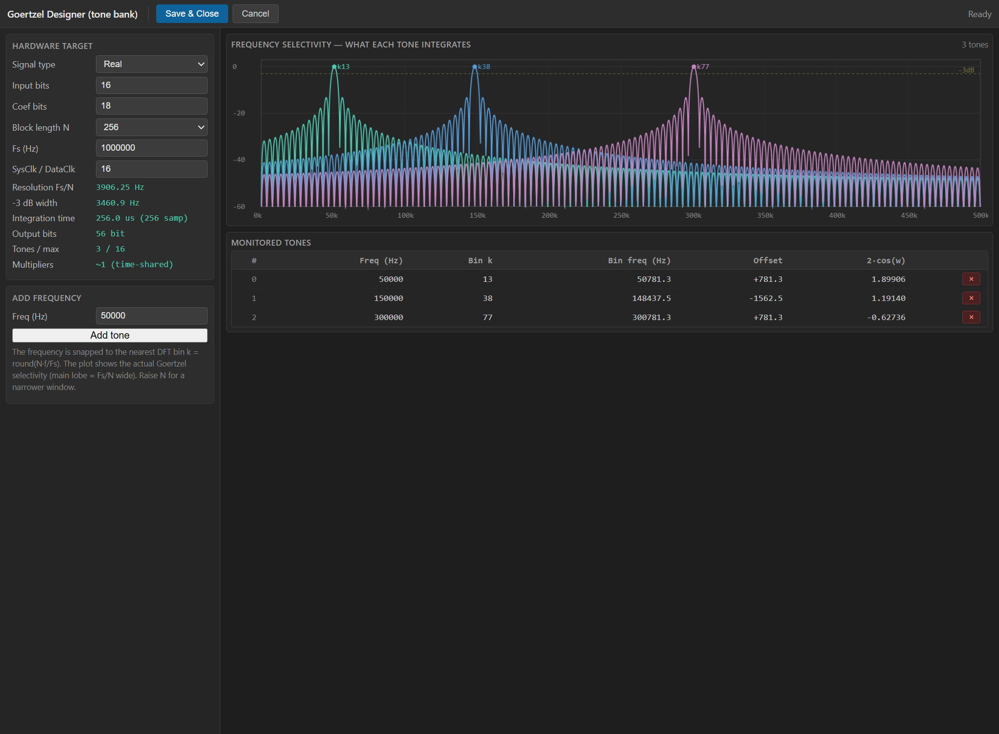
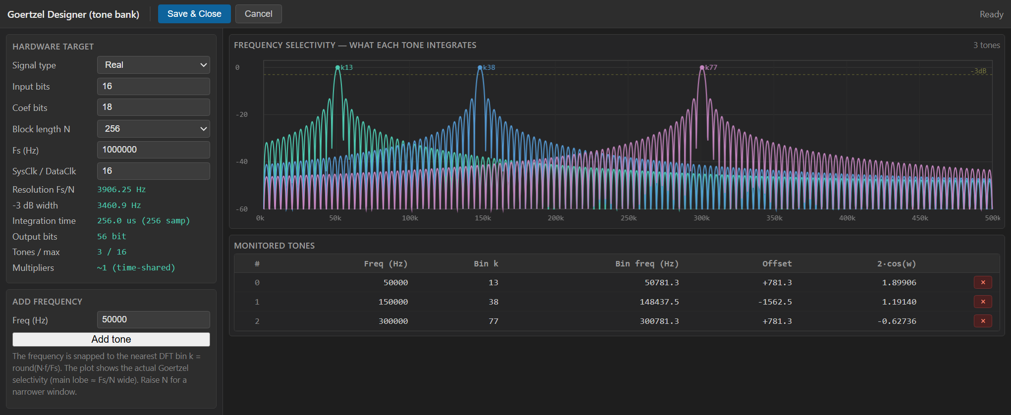
This block is configured entirely through the Goertzel Designer
(a WebView2 graphical tool), not the normal property grid.
Double-click the block to open it. In the designer you set the
hardware target (signal type, input/coefficient bit widths, block length
N, Fs) and enter the target frequency to monitor; the tool snaps it to
the nearest DFT bin k = round(N*f/Fs), draws the frequency-selectivity
plot (the actual Goertzel main lobe, ~Fs/N wide, showing what the bin
integrates) and shows a live resource / result estimate: resolution
Fs/N, -3 dB width, integration time, output bits and multiplier count.
Save & Close writes the configuration (and the quantised coefficients)
back into the block.
Typical applications
- Single-tone / pilot detection : is carrier f present, and how strong?
- DTMF and signalling-tone decoding (one Goertzel per tone frequency).
- Narrowband power / energy measurement at one spectral line.
- Coherent line tracking where a full FFT would be wasteful.
Resources & Timing
-
Latency: 1 clock per sample; a new POWER every N samples (block latency = N samples)
-
Throughput: 1 input sample per SAMPLE_IN pulse (II=1, free-running ap_ctrl_none)
Implemented with Vitis HLS. The per-sample recurrence needs a single
real multiplier (2*cos(w)); the end-of-block magnitude adds a few
more multiplies for s1^2 + s2^2 - 2cos(w) s1 s2 (real) or the
Xr^2 + Xi^2 reconstruction (complex). No BRAM is required (only the
two resonator states are kept, unlike the sliding variant). Cost is
essentially independent of N; increasing N only widens the state
registers by ceil(log2 N). Dramatically cheaper than an FFT when a
single bin is needed.