
DSP - BLOCK STATISTICS
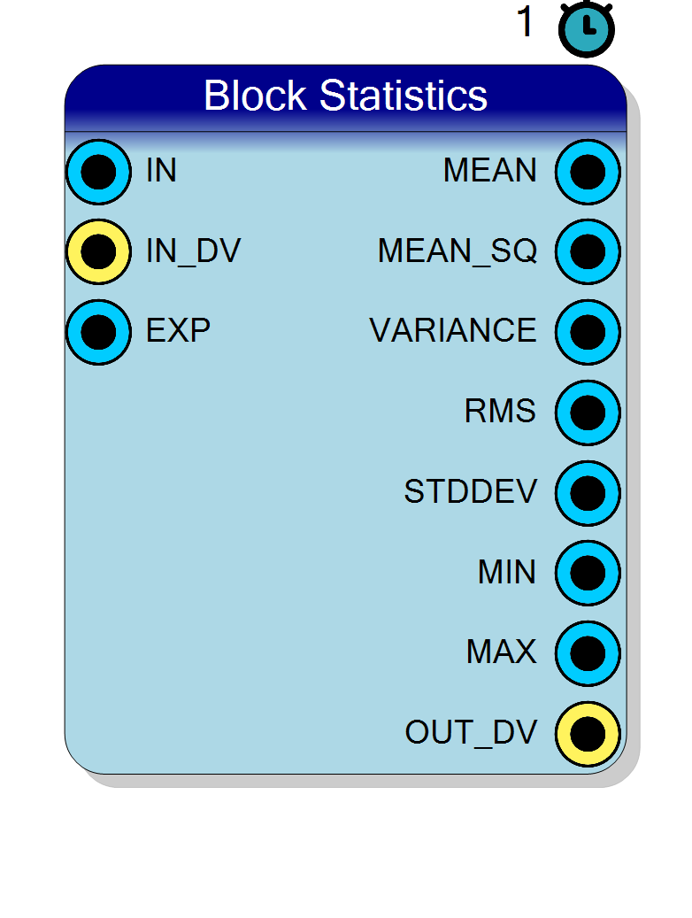
Mean, mean square, variance, RMS, standard deviation, minimum and maximum over a block of N consecutive samples. N is a power of two chosen at RUN TIME on the EXP input pin (EXP = 10 means N = 1024), so both divisions are exact arithmetic shifts and the block contains no divider at all. Every statistic has its own fixed point Q format and can be switched off, which removes its pin and its logic before synthesis. On top of mean, mean square, variance, RMS, standard deviation, min and max it can also extract the raw sums, the positive / negative / absolute area and the sample counts around a RUNTIME LEVEL, the level crossing count, the peak-to-peak, the position of the minimum and of the maximum inside the block, and the crest factor, plus BUSY / INTEGRATING / SAMPLE_COUNT status outputs. Blocks of up to 2^20 samples out of the box, 2^31 if you ask for it. Post-accumulation arithmetic is SERIAL: one reused shift-add stage for the square and one reused compare-subtract stage shared by both square roots - no DSP in the tail.
Introduction
The Block Statistics block chops the input stream into consecutive blocks of N samples and, at the end of each block, publishes a full set of first- and second-order statistics of that block:
$$ S_1 = \sum_{i=0}^{N-1} x_i , \qquad S_2 = \sum_{i=0}^{N-1} x_i^2 $$
$$ \mathrm{mean} = \frac{S_1}{N}, \qquad \overline{x^2} = \frac{S_2}{N}, \qquad \mathrm{var} = \overline{x^2} - \mathrm{mean}^2 $$
$$ \mathrm{rms} = \sqrt{\overline{x^2}}, \qquad \sigma = \sqrt{\mathrm{var}} $$
plus the smallest and the largest sample of the block.
A second family of measures is referred to a level $\ell$ driven on the
LEVEL pin (0 by default, in which case they become the usual zero-referred
ones). With $d_i = x_i - \ell$:
$$ A^{+} = !!\sum_{d_i > 0}!! d_i, \quad A^{-} = !!\sum_{d_i < 0}!! d_i, \quad A^{|\cdot|} = \sum_i |d_i| = A^{+} - A^{-}, \quad \overline{|d|} = \frac{A^{|\cdot|}}{N} $$
together with how many samples lie above the level, how many below it, and how many times the signal crosses it. Finally the block can report $\max-\min$, the positions of the minimum and the maximum inside the block, the raw accumulators $S_1$ and $S_2$ themselves, and the crest factor $\max(|\min|,|\max|)/\mathrm{rms}$.
N is a runtime input, not a property. You drive the exponent on the
EXP pin and the block size is $N = 2^{\mathrm{EXP}}$:
| EXP | N | EXP | N |
|---|---|---|---|
| 4 | 16 | 12 | 4096 |
| 6 | 64 | 16 | 65536 |
| 8 | 256 | 20 | 1048576 |
Because N is a power of two, both divisions are exact arithmetic shifts. There is no divider, no reciprocal ROM and no rounding beyond the single final requantisation into your Q format - which is also why the block size can be changed while the design is running, for free.
Typical uses: baseline and noise estimation on a detector channel, per-block RMS for a level meter or AGC, variance as a stability / pile-up indicator, min/max as a peak-to-peak or clipping detector, and general block-averaged telemetry that a slow control loop or the CPU can read.
What each measure is FOR
- MEAN - the baseline / DC level of the channel. Subtract it downstream and you have a zero-centred signal.
- MEAN_SQ and SUM_SQ - the raw second moment. Take them when you want to do your own statistics downstream (combining blocks, for instance) rather than have the block do the arithmetic for you. SUM is the same idea for the first moment, and both are free: the accumulators exist anyway.
- VARIANCE, RMS, STDDEV - three views of the same spread. RMS includes the DC level, STDDEV does not; VARIANCE is STDDEV squared and needs no square root, so it is the cheapest of the three if you only need to compare or threshold.
- MEAN_ABS - the mean absolute deviation from the level. A robust noise estimate that needs no square root at all: for Gaussian noise it is $\sigma\sqrt{2/\pi} \approx 0.8,\sigma$, and unlike the standard deviation a single large outlier moves it linearly instead of quadratically. If you are reaching for STDDEV just to get “how noisy is this”, this is usually the cheaper and steadier answer.
- POS_AREA / NEG_AREA / ABS_AREA - integrated charge above / below / around the level. In pulse processing the positive area over a baseline IS the integrated pulse; the negative area shows undershoot; the absolute area is the total activity regardless of sign.
- POS_COUNT / NEG_COUNT - duty cycle and asymmetry: what fraction of the block sits above the level. With the level set to a discriminator threshold, POS_COUNT is a time-over-threshold measure.
- ZERO_CROSS - a frequency / activity estimate that costs one comparator: for a clean sine the crossing rate is directly the frequency. With a non-zero level it becomes a level crossing counter, which is the more useful form - a hysteresis-free discriminator hit counter.
- PEAK_TO_PEAK - amplitude at a glance, and the classic clipping / saturation check.
- ARGMIN / ARGMAX - where in time the extremum happened. This is what locates a pulse inside the block: the block index of the maximum is a coarse time stamp, and the distance between ARGMIN and ARGMAX measures a pulse’s rise or fall span.
- CREST - peak over RMS. The standard “how peaky is this” number: ~1.41 for a sine, ~1 for a square wave, large for a spiky or pulsed signal. It is the one measure here that costs a divider.
Pin Description
IN_DV is high (there is deliberately
no CE pin - see “Accumulation and IN_DV”).
'1'. (There is deliberately no CE pin - see
“Accumulation and IN_DV”.)
OUT_DV clock.
OUT_DV clock.
OUT_DV
clock.
BUSY is still high here and falls on the next clock.
OUT_DV pulse, and it falls on the clock after. On a continuous
stream the next block starts before the previous tail ends, so it simply
stays high. Present only when Enable BUSY = YES.
BUSY high with INTEGRATING low therefore means “all
the samples are in, the block is computing”. Present only when
Enable INTEGRATING = YES.
OUT_DV,
until the first sample of the next block takes it back to 1, so on the
OUT_DV clock it reads the length of the block being presented. Only
RESET clears it to 0. Fixed 32 bits. Present only when
Enable SAMPLE_COUNT = YES.
Properties
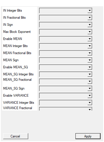
Number of INTEGER bits of the input sample (the sign, when present, uses one of them).
Integer bits of the input (the sign, when present, uses one of them). 1..64.Default: 16
Options: 1 2 3 4 5 6 7 8 9 10 11 12 13 14 15 16 17 18 19 20 21 22 23 24 25 26 27 28 29 30 31 32 33 34 35 36 37 38 39 40 41 42 43 44 45 46 47 48 49 50 51 52 53 54 55 56 57 58 59 60 61 62 63 64
Number of FRACTIONAL bits of the input sample, i.e. the bits to the right of the binary point. Total width = integer + fractional bits, and must not exceed 64.
Fractional bits of the input. 0..64. Total input width must be 2..64 bits.Default: 0
Options: 0 1 2 3 4 5 6 7 8 9 10 11 12 13 14 15 16 17 18 19 20 21 22 23 24 25 26 27 28 29 30 31 32 33 34 35 36 37 38 39 40 41 42 43 44 45 46 47 48 49 50 51 52 53 54 55 56 57 58 59 60 61 62 63 64
Select whether the input sample is signed (two’s complement) or unsigned.
SIGNED (two’s complement) or UNSIGNED input.Default: SIGNED
Options: UNSIGNED SIGNED
Largest block-size exponent the accumulators are sized for: the block can be up to 2^MaxBlockExponent samples long. The EXP input is clamped to this value at run time. Raising it widens the internal sum and sum-of-squares registers (and lengthens the serial tail by one clock per unit), so keep it at the largest block you actually use. The default of 20 covers blocks of up to 1048576 samples.
Largest block-size exponent the accumulators are sized for: the block can be up to $2^{\text{MaxBlockExponent}}$ samples long, and theEXP input
is clamped to this value at run time. Raising it widens the internal sum
and sum-of-squares registers and lengthens the serial tail by one clock
per unit, so keep it at the largest block you actually use. 1..31,
default 20, i.e. blocks of up to 1048576 samples out of the box.
Default: 20
Options: 1 2 3 4 5 6 7 8 9 10 11 12 13 14 15 16 17 18 19 20 21 22 23 24 25 26 27 28 29 30 31
YES: the MEAN pin is present. NO: the pin AND all of its logic are removed before synthesis. Note the internal dependencies: STDDEV needs the variance, the variance needs the mean and the mean square, RMS needs the mean square – those intermediates are always built when something depends on them, whether or not their own pin is enabled.
YES: theMEAN pin exists. NO: the pin and its requantiser are removed
before synthesis. The sum $S_1$ is still built if VARIANCE or STDDEV
needs it.
Default: YES
Options: NO YES
Number of INTEGER bits of the MEAN output (the sign, when present, uses one of them).
Integer bits of the MEAN output. 1..64.Default: 16
Options: 1 2 3 4 5 6 7 8 9 10 11 12 13 14 15 16 17 18 19 20 21 22 23 24 25 26 27 28 29 30 31 32 33 34 35 36 37 38 39 40 41 42 43 44 45 46 47 48 49 50 51 52 53 54 55 56 57 58 59 60 61 62 63 64
Number of FRACTIONAL bits of the MEAN output, i.e. the bits to the right of the binary point. Total width = integer + fractional bits, and must not exceed 64.
Fractional bits of the MEAN output. Total width 2..64 bits.Default: 0
Options: 0 1 2 3 4 5 6 7 8 9 10 11 12 13 14 15 16 17 18 19 20 21 22 23 24 25 26 27 28 29 30 31 32 33 34 35 36 37 38 39 40 41 42 43 44 45 46 47 48 49 50 51 52 53 54 55 56 57 58 59 60 61 62 63 64
Select whether the MEAN output is signed (two’s complement) or unsigned.
SIGNED or UNSIGNED MEAN output. Use SIGNED for a bipolar signal.Default: SIGNED
Options: UNSIGNED SIGNED
YES: the MEAN_SQ (the mean of x*x) pin is present. NO: the pin AND all of its logic are removed before synthesis. Note the internal dependencies: STDDEV needs the variance, the variance needs the mean and the mean square, RMS needs the mean square – those intermediates are always built when something depends on them, whether or not their own pin is enabled.
YES: theMEAN_SQ pin exists. NO: the pin and its requantiser are
removed. The sum of squares $S_2$ is still built if RMS, VARIANCE or
STDDEV needs it.
Default: YES
Options: NO YES
Number of INTEGER bits of the MEAN_SQ output (the sign, when present, uses one of them).
Integer bits of the MEAN_SQ output. It is a SQUARE: allow about twice the input integer bits.Default: 32
Options: 1 2 3 4 5 6 7 8 9 10 11 12 13 14 15 16 17 18 19 20 21 22 23 24 25 26 27 28 29 30 31 32 33 34 35 36 37 38 39 40 41 42 43 44 45 46 47 48 49 50 51 52 53 54 55 56 57 58 59 60 61 62 63 64
Number of FRACTIONAL bits of the MEAN_SQ output, i.e. the bits to the right of the binary point. Total width = integer + fractional bits, and must not exceed 64.
Fractional bits of the MEAN_SQ output. Total width 2..64 bits.Default: 0
Options: 0 1 2 3 4 5 6 7 8 9 10 11 12 13 14 15 16 17 18 19 20 21 22 23 24 25 26 27 28 29 30 31 32 33 34 35 36 37 38 39 40 41 42 43 44 45 46 47 48 49 50 51 52 53 54 55 56 57 58 59 60 61 62 63 64
Select whether the MEAN_SQ output is signed (two’s complement) or unsigned.
SIGNED or UNSIGNED. The mean square is never negative, so UNSIGNED buys one bit.Default: UNSIGNED
Options: UNSIGNED SIGNED
YES: the VARIANCE pin is present. NO: the pin AND all of its logic are removed before synthesis. Note the internal dependencies: STDDEV needs the variance, the variance needs the mean and the mean square, RMS needs the mean square – those intermediates are always built when something depends on them, whether or not their own pin is enabled.
YES: theVARIANCE pin exists. NO: the pin and its requantiser are
removed. The variance numerator is still built if STDDEV needs it.
Default: YES
Options: NO YES
Number of INTEGER bits of the VARIANCE output (the sign, when present, uses one of them).
Integer bits of the VARIANCE output. It is a SQUARE: allow about twice the input integer bits.Default: 32
Options: 1 2 3 4 5 6 7 8 9 10 11 12 13 14 15 16 17 18 19 20 21 22 23 24 25 26 27 28 29 30 31 32 33 34 35 36 37 38 39 40 41 42 43 44 45 46 47 48 49 50 51 52 53 54 55 56 57 58 59 60 61 62 63 64
Number of FRACTIONAL bits of the VARIANCE output, i.e. the bits to the right of the binary point. Total width = integer + fractional bits, and must not exceed 64.
Fractional bits of the VARIANCE output. Total width 2..64 bits.Default: 0
Options: 0 1 2 3 4 5 6 7 8 9 10 11 12 13 14 15 16 17 18 19 20 21 22 23 24 25 26 27 28 29 30 31 32 33 34 35 36 37 38 39 40 41 42 43 44 45 46 47 48 49 50 51 52 53 54 55 56 57 58 59 60 61 62 63 64
Select whether the VARIANCE output is signed (two’s complement) or unsigned.
SIGNED or UNSIGNED. The variance is clamped at zero, so UNSIGNED is safe and buys one bit.Default: UNSIGNED
Options: UNSIGNED SIGNED
YES: the RMS pin is present. NO: the pin AND all of its logic are removed before synthesis. Note the internal dependencies: STDDEV needs the variance, the variance needs the mean and the mean square, RMS needs the mean square – those intermediates are always built when something depends on them, whether or not their own pin is enabled.
YES: theRMS pin exists and one square-root run is scheduled in the
serial tail. NO: both are removed, which shortens the tail by RTW + 1
clocks.
Default: YES
Options: NO YES
Number of INTEGER bits of the RMS output (the sign, when present, uses one of them).
Integer bits of the RMS output. RMS is in the units of the input, so the input integer bits are a good default.Default: 16
Options: 1 2 3 4 5 6 7 8 9 10 11 12 13 14 15 16 17 18 19 20 21 22 23 24 25 26 27 28 29 30 31 32 33 34 35 36 37 38 39 40 41 42 43 44 45 46 47 48 49 50 51 52 53 54 55 56 57 58 59 60 61 62 63 64
Number of FRACTIONAL bits of the RMS output, i.e. the bits to the right of the binary point. Total width = integer + fractional bits, and must not exceed 64.
Fractional bits of the RMS output. Total width 2..64 bits. The total width sets the length of the serial square root (RTW = width + 5 steps), so do not make it wider than you need.Default: 0
Options: 0 1 2 3 4 5 6 7 8 9 10 11 12 13 14 15 16 17 18 19 20 21 22 23 24 25 26 27 28 29 30 31 32 33 34 35 36 37 38 39 40 41 42 43 44 45 46 47 48 49 50 51 52 53 54 55 56 57 58 59 60 61 62 63 64
Select whether the RMS output is signed (two’s complement) or unsigned.
SIGNED or UNSIGNED. The RMS is never negative, so UNSIGNED buys one bit.Default: UNSIGNED
Options: UNSIGNED SIGNED
YES: the STDDEV pin is present. NO: the pin AND all of its logic are removed before synthesis. Note the internal dependencies: STDDEV needs the variance, the variance needs the mean and the mean square, RMS needs the mean square – those intermediates are always built when something depends on them, whether or not their own pin is enabled.
YES: theSTDDEV pin exists and a second square-root run is scheduled in
the serial tail. NO: both are removed, which shortens the tail by
RTW + 1 clocks. STDDEV pulls in the variance datapath internally even
when the VARIANCE pin is disabled.
Default: YES
Options: NO YES
Number of INTEGER bits of the STDDEV output (the sign, when present, uses one of them).
Integer bits of the STDDEV output. It is in the units of the input.Default: 16
Options: 1 2 3 4 5 6 7 8 9 10 11 12 13 14 15 16 17 18 19 20 21 22 23 24 25 26 27 28 29 30 31 32 33 34 35 36 37 38 39 40 41 42 43 44 45 46 47 48 49 50 51 52 53 54 55 56 57 58 59 60 61 62 63 64
Number of FRACTIONAL bits of the STDDEV output, i.e. the bits to the right of the binary point. Total width = integer + fractional bits, and must not exceed 64.
Fractional bits of the STDDEV output. Total width 2..64 bits; it also sets the square-root length.Default: 0
Options: 0 1 2 3 4 5 6 7 8 9 10 11 12 13 14 15 16 17 18 19 20 21 22 23 24 25 26 27 28 29 30 31 32 33 34 35 36 37 38 39 40 41 42 43 44 45 46 47 48 49 50 51 52 53 54 55 56 57 58 59 60 61 62 63 64
Select whether the STDDEV output is signed (two’s complement) or unsigned.
SIGNED or UNSIGNED. The standard deviation is never negative, so UNSIGNED buys one bit.Default: UNSIGNED
Options: UNSIGNED SIGNED
YES: the MIN and MAX pins are present. NO: they and their comparators are removed at elaboration. MIN and MAX are returned in the INPUT Q format – they are actual samples, so no other format makes sense.
YES: theMIN and MAX pins exist. NO: they and their comparators are
removed. MIN and MAX are returned in the INPUT Q format - they are actual
samples, so no other format makes sense. They do not lengthen the tail.
Default: YES
Options: NO YES
YES: the SUM (the raw sum of the samples, S1) pin is present. NO: the pin AND all of its logic are removed before synthesis. Off by default.
YES: theSUM pin exists. NO: the pin and its requantiser are removed.
Free either way - the accumulator is there for the mean anyway. Default
NO.
Default: NO
Options: NO YES
Number of INTEGER bits of the SUM output (the sign, when present, uses one of them).
Integer bits of the SUM output. It holds N samples: allow input bits + Max Block Exponent.Default: 24
Options: 1 2 3 4 5 6 7 8 9 10 11 12 13 14 15 16 17 18 19 20 21 22 23 24 25 26 27 28 29 30 31 32 33 34 35 36 37 38 39 40 41 42 43 44 45 46 47 48 49 50 51 52 53 54 55 56 57 58 59 60 61 62 63 64
Number of FRACTIONAL bits of the SUM output, i.e. the bits to the right of the binary point. Total width = integer + fractional bits, and must not exceed 64.
Fractional bits of the SUM output. Total width 2..64 bits.Default: 0
Options: 0 1 2 3 4 5 6 7 8 9 10 11 12 13 14 15 16 17 18 19 20 21 22 23 24 25 26 27 28 29 30 31 32 33 34 35 36 37 38 39 40 41 42 43 44 45 46 47 48 49 50 51 52 53 54 55 56 57 58 59 60 61 62 63 64
Select whether the SUM output is signed (two’s complement) or unsigned.
SIGNED or UNSIGNED. A sum of signed samples needs SIGNED.Default: SIGNED
Options: UNSIGNED SIGNED
YES: the SUM_SQ (the raw sum of the squares, S2) pin is present. NO: the pin AND all of its logic are removed before synthesis. Off by default.
YES: theSUM_SQ pin exists. NO: the pin and its requantiser are
removed. Free either way. Default NO.
Default: NO
Options: NO YES
Number of INTEGER bits of the SUM_SQ output (the sign, when present, uses one of them).
Integer bits of the SUM_SQ output. It holds N SQUARES: allow 2x input bits + Max Block Exponent.Default: 40
Options: 1 2 3 4 5 6 7 8 9 10 11 12 13 14 15 16 17 18 19 20 21 22 23 24 25 26 27 28 29 30 31 32 33 34 35 36 37 38 39 40 41 42 43 44 45 46 47 48 49 50 51 52 53 54 55 56 57 58 59 60 61 62 63 64
Number of FRACTIONAL bits of the SUM_SQ output, i.e. the bits to the right of the binary point. Total width = integer + fractional bits, and must not exceed 64.
Fractional bits of the SUM_SQ output. Total width 2..64 bits.Default: 0
Options: 0 1 2 3 4 5 6 7 8 9 10 11 12 13 14 15 16 17 18 19 20 21 22 23 24 25 26 27 28 29 30 31 32 33 34 35 36 37 38 39 40 41 42 43 44 45 46 47 48 49 50 51 52 53 54 55 56 57 58 59 60 61 62 63 64
Select whether the SUM_SQ output is signed (two’s complement) or unsigned.
SIGNED or UNSIGNED. A sum of squares is never negative, so UNSIGNED buys one bit.Default: UNSIGNED
Options: UNSIGNED SIGNED
YES: the POS_AREA (the sum of the samples ABOVE the LEVEL, measured from it) pin is present. NO: the pin AND all of its logic are removed before synthesis. Off by default.
YES: thePOS_AREA pin exists and one accumulator is added. NO: both are
removed. Default NO.
Default: NO
Options: NO YES
Number of INTEGER bits of the POS_AREA output (the sign, when present, uses one of them).
Integer bits of the POS_AREA output. It integrates up to N deviations: allow input bits + Max Block Exponent.Default: 24
Options: 1 2 3 4 5 6 7 8 9 10 11 12 13 14 15 16 17 18 19 20 21 22 23 24 25 26 27 28 29 30 31 32 33 34 35 36 37 38 39 40 41 42 43 44 45 46 47 48 49 50 51 52 53 54 55 56 57 58 59 60 61 62 63 64
Number of FRACTIONAL bits of the POS_AREA output, i.e. the bits to the right of the binary point. Total width = integer + fractional bits, and must not exceed 64.
Fractional bits of the POS_AREA output. Total width 2..64 bits.Default: 0
Options: 0 1 2 3 4 5 6 7 8 9 10 11 12 13 14 15 16 17 18 19 20 21 22 23 24 25 26 27 28 29 30 31 32 33 34 35 36 37 38 39 40 41 42 43 44 45 46 47 48 49 50 51 52 53 54 55 56 57 58 59 60 61 62 63 64
Select whether the POS_AREA output is signed (two’s complement) or unsigned.
SIGNED or UNSIGNED. The positive area is never negative, so UNSIGNED buys one bit.Default: UNSIGNED
Options: UNSIGNED SIGNED
YES: the NEG_AREA (the sum of the samples BELOW the LEVEL, measured from it; it is negative or zero) pin is present. NO: the pin AND all of its logic are removed before synthesis. Off by default.
YES: theNEG_AREA pin exists and one accumulator is added. NO: both are
removed. Default NO.
Default: NO
Options: NO YES
Number of INTEGER bits of the NEG_AREA output (the sign, when present, uses one of them).
Integer bits of the NEG_AREA output.Default: 24
Options: 1 2 3 4 5 6 7 8 9 10 11 12 13 14 15 16 17 18 19 20 21 22 23 24 25 26 27 28 29 30 31 32 33 34 35 36 37 38 39 40 41 42 43 44 45 46 47 48 49 50 51 52 53 54 55 56 57 58 59 60 61 62 63 64
Number of FRACTIONAL bits of the NEG_AREA output, i.e. the bits to the right of the binary point. Total width = integer + fractional bits, and must not exceed 64.
Fractional bits of the NEG_AREA output. Total width 2..64 bits.Default: 0
Options: 0 1 2 3 4 5 6 7 8 9 10 11 12 13 14 15 16 17 18 19 20 21 22 23 24 25 26 27 28 29 30 31 32 33 34 35 36 37 38 39 40 41 42 43 44 45 46 47 48 49 50 51 52 53 54 55 56 57 58 59 60 61 62 63 64
Select whether the NEG_AREA output is signed (two’s complement) or unsigned.
SIGNED or UNSIGNED. The negative area is NEGATIVE, so use SIGNED unless you only want the magnitude to wrap.Default: SIGNED
Options: UNSIGNED SIGNED
YES: the ABS_AREA (the sum of |sample - LEVEL|). It is DERIVED as POS_AREA - NEG_AREA, one subtraction, so it costs no third accumulator – but it does pull BOTH area accumulators in pin is present. NO: the pin AND all of its logic are removed before synthesis. Off by default.
YES: theABS_AREA pin exists. It is derived as POS_AREA - NEG_AREA, so
it costs one subtraction and no third accumulator - but it does pull BOTH
area accumulators in, whether or not their own pins are on. Default NO.
Default: NO
Options: NO YES
Number of INTEGER bits of the ABS_AREA output (the sign, when present, uses one of them).
Integer bits of the ABS_AREA output. It is the sum of the two areas: allow one bit more than either.Default: 24
Options: 1 2 3 4 5 6 7 8 9 10 11 12 13 14 15 16 17 18 19 20 21 22 23 24 25 26 27 28 29 30 31 32 33 34 35 36 37 38 39 40 41 42 43 44 45 46 47 48 49 50 51 52 53 54 55 56 57 58 59 60 61 62 63 64
Number of FRACTIONAL bits of the ABS_AREA output, i.e. the bits to the right of the binary point. Total width = integer + fractional bits, and must not exceed 64.
Fractional bits of the ABS_AREA output. Total width 2..64 bits.Default: 0
Options: 0 1 2 3 4 5 6 7 8 9 10 11 12 13 14 15 16 17 18 19 20 21 22 23 24 25 26 27 28 29 30 31 32 33 34 35 36 37 38 39 40 41 42 43 44 45 46 47 48 49 50 51 52 53 54 55 56 57 58 59 60 61 62 63 64
Select whether the ABS_AREA output is signed (two’s complement) or unsigned.
SIGNED or UNSIGNED. The absolute area is never negative, so UNSIGNED buys one bit.Default: UNSIGNED
Options: UNSIGNED SIGNED
YES: the MEAN_ABS (ABS_AREA / N, the mean absolute deviation from the LEVEL). One extra shift on the same value, so it also pulls both area accumulators in pin is present. NO: the pin AND all of its logic are removed before synthesis. Off by default.
YES: theMEAN_ABS pin exists. Same value as ABS_AREA with one more
shift, so it also pulls both area accumulators in. Default NO.
Default: NO
Options: NO YES
Number of INTEGER bits of the MEAN_ABS output (the sign, when present, uses one of them).
Integer bits of the MEAN_ABS output. It is in the units of the input, so the input integer bits are a good default.Default: 16
Options: 1 2 3 4 5 6 7 8 9 10 11 12 13 14 15 16 17 18 19 20 21 22 23 24 25 26 27 28 29 30 31 32 33 34 35 36 37 38 39 40 41 42 43 44 45 46 47 48 49 50 51 52 53 54 55 56 57 58 59 60 61 62 63 64
Number of FRACTIONAL bits of the MEAN_ABS output, i.e. the bits to the right of the binary point. Total width = integer + fractional bits, and must not exceed 64.
Fractional bits of the MEAN_ABS output. Total width 2..64 bits.Default: 0
Options: 0 1 2 3 4 5 6 7 8 9 10 11 12 13 14 15 16 17 18 19 20 21 22 23 24 25 26 27 28 29 30 31 32 33 34 35 36 37 38 39 40 41 42 43 44 45 46 47 48 49 50 51 52 53 54 55 56 57 58 59 60 61 62 63 64
Select whether the MEAN_ABS output is signed (two’s complement) or unsigned.
SIGNED or UNSIGNED. The mean absolute deviation is never negative, so UNSIGNED buys one bit.Default: UNSIGNED
Options: UNSIGNED SIGNED
YES: the POS_COUNT (how many samples of the block are strictly ABOVE the LEVEL) pin is present. NO: the pin AND all of its logic are removed before synthesis. Off by default.
YES: thePOS_COUNT pin exists and one counter is added. NO: both are
removed. The width is fixed by Max Block Exponent, there is no Q
format. Default NO.
Default: NO
Options: NO YES
YES: the NEG_COUNT (how many samples of the block are strictly BELOW the LEVEL) pin is present. NO: the pin AND all of its logic are removed before synthesis. Off by default.
YES: theNEG_COUNT pin exists and one counter is added. NO: both are
removed. Default NO.
Default: NO
Options: NO YES
YES: the ZERO_CROSS (how many times the signal crosses the LEVEL during the block). Samples sitting exactly ON the level are ignored, and the sign memory carries over from the previous block pin is present. NO: the pin AND all of its logic are removed before synthesis. Off by default.
YES: theZERO_CROSS pin exists, along with one counter and a two-bit
sign memory. NO: all of it is removed. Default NO.
Default: NO
Options: NO YES
YES: the PEAK_TO_PEAK (MAX - MIN). One subtraction, but it pulls the min/max registers in even when their pins are off pin is present. NO: the pin AND all of its logic are removed before synthesis. Off by default.
YES: thePEAK_TO_PEAK pin exists. One subtraction, but it pulls the
min/max registers in even when the MIN and MAX pins are disabled.
Default NO.
Default: NO
Options: NO YES
Number of INTEGER bits of the PEAK_TO_PEAK output (the sign, when present, uses one of them).
Integer bits of the PEAK_TO_PEAK output. It can reach the full input span, so allow one bit more than the input.Default: 17
Options: 1 2 3 4 5 6 7 8 9 10 11 12 13 14 15 16 17 18 19 20 21 22 23 24 25 26 27 28 29 30 31 32 33 34 35 36 37 38 39 40 41 42 43 44 45 46 47 48 49 50 51 52 53 54 55 56 57 58 59 60 61 62 63 64
Number of FRACTIONAL bits of the PEAK_TO_PEAK output, i.e. the bits to the right of the binary point. Total width = integer + fractional bits, and must not exceed 64.
Fractional bits of the PEAK_TO_PEAK output. Total width 2..64 bits.Default: 0
Options: 0 1 2 3 4 5 6 7 8 9 10 11 12 13 14 15 16 17 18 19 20 21 22 23 24 25 26 27 28 29 30 31 32 33 34 35 36 37 38 39 40 41 42 43 44 45 46 47 48 49 50 51 52 53 54 55 56 57 58 59 60 61 62 63 64
Select whether the PEAK_TO_PEAK output is signed (two’s complement) or unsigned.
SIGNED or UNSIGNED. MAX - MIN is never negative, so UNSIGNED buys one bit.Default: UNSIGNED
Options: UNSIGNED SIGNED
YES: the ARGMIN (the INDEX inside the block at which the minimum occurred; the FIRST one if it occurs more than once). Pulls the min/max registers in pin is present. NO: the pin AND all of its logic are removed before synthesis. Off by default.
YES: theARGMIN pin exists, along with one index register. It pulls the
min/max registers in. The width follows Max Block Exponent; there is no
Q format. Default NO.
Default: NO
Options: NO YES
YES: the ARGMAX (the INDEX inside the block at which the maximum occurred; the FIRST one if it occurs more than once). Pulls the min/max registers in pin is present. NO: the pin AND all of its logic are removed before synthesis. Off by default.
YES: theARGMAX pin exists, along with one index register. It pulls the
min/max registers in. Default NO.
Default: NO
Options: NO YES
YES: the CREST (peak / rms, with peak = max(|MIN|, |MAX|)). THIS IS THE ONLY STATISTIC THAT COSTS A DIVIDER: it adds a serial restoring division to the tail and therefore LENGTHENS the latency. It pulls in the min/max registers and the rms square root even when their pins are off pin is present. NO: the pin AND all of its logic are removed before synthesis. Off by default.
YES: theCREST pin exists. This is the only statistic that costs a
divider: it adds a serial restoring division to the tail and therefore
LENGTHENS the latency (by CNUMW + 1 clocks) and can raise the
minimum usable block exponent. It pulls in the min/max registers and the
RMS square root even when their own pins are off - and the RMS Q format
still sizes that internal root. NO removes all of it at preprocessing and
the latency goes back to exactly what it was. Default NO.
Default: NO
Options: NO YES
Number of INTEGER bits of the CREST output (the sign, when present, uses one of them).
Integer bits of the CREST output. A crest factor is ~1.41 for a sine and ~1 for a square wave, so 4 integer bits (up to 15) is generous for a real signal; raise it only for very spiky data.Default: 4
Options: 1 2 3 4 5 6 7 8 9 10 11 12 13 14 15 16 17 18 19 20 21 22 23 24 25 26 27 28 29 30 31 32 33 34 35 36 37 38 39 40 41 42 43 44 45 46 47 48 49 50 51 52 53 54 55 56 57 58 59 60 61 62 63 64
Number of FRACTIONAL bits of the CREST output, i.e. the bits to the right of the binary point. Total width = integer + fractional bits, and must not exceed 64.
Fractional bits of the CREST output. This is where the resolution goes: the default 12 bits give steps of 1/4096. The total width also sets the number of division steps, so do not make it wider than you need.Default: 12
Options: 0 1 2 3 4 5 6 7 8 9 10 11 12 13 14 15 16 17 18 19 20 21 22 23 24 25 26 27 28 29 30 31 32 33 34 35 36 37 38 39 40 41 42 43 44 45 46 47 48 49 50 51 52 53 54 55 56 57 58 59 60 61 62 63 64
Select whether the CREST output is signed (two’s complement) or unsigned.
SIGNED or UNSIGNED. A crest factor is never negative, so UNSIGNED buys one bit.Default: UNSIGNED
Options: UNSIGNED SIGNED
YES: the BUSY (high from the first sample of a block until its result is out – it COVERS THE SERIAL TAIL, and its last clock is the OUT_DV pulse) pin is present. NO: the pin AND all of its logic are removed before synthesis. Off by default.
YES: theBUSY pin exists. It is high from the first sample of a block
until its result is out, tail included, and its last clock is the
OUT_DV pulse. Default NO.
Default: NO
Options: NO YES
YES: the INTEGRATING (high only while the block is ACCUMULATING; it drops as soon as the N-th sample has been taken and the tail starts, so BUSY-and-not-INTEGRATING means ‘computing’) pin is present. NO: the pin AND all of its logic are removed before synthesis. Off by default.
YES: theINTEGRATING pin exists. It is high only while the block is
accumulating, so BUSY and INTEGRATING together say which phase the
block is in. Default NO.
Default: NO
Options: NO YES
YES: the SAMPLE_COUNT (32 bit, how many samples have been accumulated so far in the current block; it HOLDS the final count through the tail and past OUT_DV until the next block starts) pin is present. NO: the pin AND all of its logic are removed before synthesis. Off by default.
YES: theSAMPLE_COUNT pin exists - a fixed 32 bit count of the samples
accumulated so far in the current block, holding the final count through
the tail and past OUT_DV. Default NO.
Default: NO
Options: NO YES
ROUND: round to nearest when a result has to be requantised into a coarser output format. TRUNCATE: drop the bits (cheaper, adds a negative bias).
ROUND: round to nearest when a result has to be requantised into a coarser output format. TRUNCATE: drop the bits (cheaper, adds a negative bias).Default: ROUND
Options: TRUNCATE ROUND
YES: clip to the largest representable value of each output format (symmetric for signed formats). NO: wrap around.
YES: clip to the largest representable value of each output format (symmetric bounds for signed formats). NO: wrap around. Only matters when an output format is too narrow for the value.Default: YES
Options: NO YES
Exactness
The variance is not computed as the difference of two truncated quotients. It is computed from the exact integer numerator
$$ \mathrm{var} = \frac{N,S_2 - S_1^2}{N^2} $$
where $N S_2$ is a shift and $S_1^2$ is an exact integer square. As a consequence:
MEAN,MEAN_SQ,VARIANCE,MINandMAXare bit exact - the only rounding is the single requantisation into the output Q format;RMSandSTDDEVare within 1 LSB of the correctly rounded value (the two square roots are digit recurrences run with 4 guard bits below the output LSB).SUM,SUM_SQ,POS_AREA,NEG_AREA,ABS_AREA,MEAN_ABS, the three counts,PEAK_TO_PEAK,ARGMINandARGMAXare bit exact as well: they are plain integer accumulators, counters and one subtraction, and the division by N inMEAN_ABSis a shift like every other division here.CRESTis the only one with a compounded error: it divides by the RMS root, which is itself accurate to about 1 LSB, and the quotient is truncated. The relative error is therefore about one part in the RMS root - a fraction of a percent for any signal with a meaningful RMS.
$N S_2 - S_1^2 = \sum_{i<j} (x_i-x_j)^2$ is mathematically non negative, so
the variance can never come out negative. The block nevertheless clamps
the numerator at zero before using it: that is what makes an unsigned
VARIANCE output format safe and what keeps a negative radicand out of the
square root. With the exact formulation above the clamp never fires; if you
ever see VARIANCE = 0 on a signal that is not constant, the value was
simply smaller than one LSB of the format you chose.
Accumulation and IN_DV
IN_DV is the only qualifier. It says “this clock carries a sample”: a
sample is accumulated, and counts towards N, exactly on the clocks where
IN_DV is high. Clocks with IN_DV low are ignored completely - whatever
sits on IN during them cannot corrupt the block - while the serial
post-processing keeps running, which is what you want: the tail has nothing
to do with the input stream. IN_DV ties to '1' when left unconnected, so
a design that simply streams samples in needs nothing wired.
There is deliberately no CE pin. An earlier revision had one and it was removed. It duplicated
IN_DV- a block that only accumulates onIN_DVhas no need to be frozen, and there is no reason to stall the tail - and it did not survive synthesis: with nothing but the internal state machine gated by it, Vitis could reason the frozen path away and delete the port from the generated IP while the wrapper still wired it, which failed a real Vivado build with [VRFC 10-718] formal port <ce> does not exist. If you need to stall this block, gate itsIN_DV.
The LEVEL pin, and what counts as “above” and “below”
LEVEL is an input pin in the input Q format. It defaults to 0 when left
unconnected, which makes the level-referred family degenerate into the usual
zero-referred one. It appears on the symbol only when at least one
level-referred statistic is enabled. Like EXP, it is latched on the first
accepted sample of a block, so a mid-block change takes effect on the next
block and a block is never split between two levels.
With $d = x - \ell$:
- $d > 0$ is above, $d < 0$ is below;
- a sample sitting exactly on the level ($d = 0$) is neither. It is
counted in neither
POS_COUNTnorNEG_COUNT, it contributes 0 to both areas (which is the same thing), and it is ignored by the crossing detector - it neither counts as a crossing nor breaks the run of the previous sign. A flat signal sitting exactly on the level therefore reports 0 crossings, not one per sample.
Crossings across a block boundary
The crossing detector’s sign memory carries over from one block to the
next: the predecessor of the first sample of a block is the last sample of
the previous block that was not exactly on the level. The stream is
continuous, and resetting the memory at every boundary would systematically
lose one crossing per block. The memory is cleared only by RESET, so the
very first sample after a reset can never produce a crossing. One
consequence worth knowing: if LEVEL changes between two blocks, the carried
sign was measured against the previous level, so exactly one comparison at
the start of the new block refers to the old one.
Ties on ARGMIN / ARGMAX
If the minimum (or maximum) occurs more than once in a block, the reported index is the first occurrence.
CREST, and what happens when the RMS is zero
CREST is $\mathrm{peak}/\mathrm{rms}$ with
$\mathrm{peak} = \max(|\mathrm{MIN}|, |\mathrm{MAX}|)$ - the usual
definition, not MAX alone, so a signal whose negative excursion is the
larger one reports that excursion. It needs the min/max registers and the RMS
square root, and pulls both in even when their own pins are disabled (the RMS
Q format properties still size the internal root that CREST divides by).
RMS can legitimately be zero - an all-zero block. Then:
| peak | rms | CREST reports |
|---|---|---|
| > 0 | 0 | the largest value the CREST format can represent (the ratio is unbounded) |
| 0 | 0 | 0 (a flat zero signal has no crest) |
Note that “rms = 0” here means the internal RMS root truncating to zero, which happens a little before the true RMS reaches zero: for a very long block containing almost nothing but zeros the RMS can fall below one root LSB. That case saturates too, which is the right answer - the ratio really is enormous.
Both are forced explicitly, independently of the Saturation property, because neither is a requantisation overflow - they are the ratio itself breaking down.
CREST is the only statistic in this block that costs a divider, which is why it is off by default and why it is the only added statistic that lengthens the serial tail (see below).
Knowing where the block is: BUSY, INTEGRATING and SAMPLE_COUNT
The three status outputs answer different questions, and the difference matters:
INTEGRATING |
BUSY |
|
|---|---|---|
| accumulating the block | 1 | 1 |
| serial tail computing | 0 | 1 |
| idle | 0 | 0 |
So BUSY covers the whole job - from the first sample of a block until
its result is out, tail included - while INTEGRATING covers only the
input phase. BUSY high with INTEGRATING low means “the samples are all
in, I am computing”. On a continuous stream the next block starts before the
previous tail ends, so BUSY simply stays high and INTEGRATING dips for a
single clock at each block boundary - which makes it a convenient block
marker.
Every output of this block is a register, so each status bit is observed on the clock after the event that sets it:
INTEGRATINGrises on the clock after the first sample of a block is accepted, and falls on the clock after the N-th is accepted.BUSYrises withINTEGRATING, stays high across the tail, is still high on theOUT_DVclock, and falls on the clock after it. The last clock ofBUSYand theOUT_DVpulse coincide.SAMPLE_COUNTreads 1 after the first accepted sample and N after the N-th. It is not cleared when the block ends: it holds the final count N through the whole tail and pastOUT_DV, until the first sample of the next block takes it back to 1. So on theOUT_DVclock it reads the length of the block whose result is being presented - which is the useful thing to latch alongside the results. OnlyRESETclears it to 0.
SAMPLE_COUNT is a fixed 32 bits, which covers any block this block can
integrate.
When EXP changes
EXP is sampled on the first accepted sample of a block and held for the
whole block. A change therefore takes effect on the next block: a block
in progress always finishes against the N it was started with, and can never
be emitted against a different N than the one it was accumulated with.
Values above Max Block Exponent are clamped to Max Block Exponent.
Timing: the serial tail
All post-accumulation arithmetic is serial - the block has a whole block period of slack after the N-th sample, so there is no reason to build a parallel datapath for it:
- $|S_1|\cdot|S_1|$ is one reused shift-add stage stepped $\mathrm{IN_SW} + \mathrm{EXP}$ times ($\mathrm{IN_SW}$ = input width, +1 bit if the input is unsigned);
- both square roots share one reused compare-subtract stage, run back to back (first RMS, then STDDEV), $\mathrm{RTW}$ steps each with $\mathrm{RTW}$ = output width + 5.
OUT_DV pulses for one clock when the tail completes, not when the N-th
sample arrives, and every enabled output is updated on that same clock. The
latency from the N-th accepted sample to the OUT_DV pulse, counted in
clocks, is
$$ L = 2 + \underbrace{(\mathrm{IN_SW} + \mathrm{EXP} + 1)}{\text{if VARIANCE or STDDEV}} + \underbrace{(\mathrm{RTW} + 1)}{\text{if RMS or CREST}} + \underbrace{(\mathrm{RTW} + 1)}{\text{if STDDEV}} + \underbrace{(\mathrm{CNUMW} + 1)}{\text{if CREST}} $$
Only CREST adds a term. Every other statistic in this block - the areas, the counts, the crossings, peak-to-peak, argmin/argmax, the raw sums, mean_abs - is an accumulator, a counter or one subtraction evaluated during the window or in the same final state as everything else, so switching them on does not change $L$ by a single clock. With CREST off the formula is exactly what it was before CREST existed.
$\mathrm{CNUMW}$, the number of division steps, is $\max(\mathrm{IN_SW} + 1 + \max(K,0),\ \mathrm{CREST\ width} + 2)$ with $K = \mathrm{CREST_{fract}} - \mathrm{IN_{fract}} + \mathrm{RMS_{fract}} + 4$; for a 16-bit input and the default Q4.12 crest format that is 34 extra clocks.
Minimum usable exponent
The tail of one block must finish before the next block completes, i.e.
$$ 2^{\mathrm{EXP}} \ge L $$
If a block completes while the previous tail is still running, that block’s
result is dropped - no OUT_DV for it. The accumulators stay correct and
the following blocks are unaffected, but a result is skipped. Choose EXP
above the minimum for your configuration; the compiler prints it in the
compilation log, and the property window refuses a configuration whose
minimum exceeds Max Block Exponent.
Worked examples (all statistics enabled):
| Input | RMS / STDDEV | RTW | L at that EXP | minimum EXP |
|---|---|---|---|---|
| 8 bit s | 10 bit | 15 | 49 at EXP = 6 | 6 (N = 64) |
| 16 bit s | 16 bit | 21 | 63 + EXP | 7 (N = 128) |
| 16 bit s | 18 bit | 23 | 74 at EXP = 7 | 7 (N = 128) |
Disabling statistics shortens the tail a lot: MEAN + MIN/MAX only gives $L = 2$ (minimum EXP = 1), RMS only gives $L = \mathrm{RTW} + 3$. Enabling CREST is the only thing that lengthens it - and it is the only thing that can raise the minimum usable exponent.
Q formats
Every port carries its own fixed point format (integer bits, fractional bits, sign), the same convention as the Fixed P. family. Results are requantised into that format with the selected rounding (nearest / truncate) and overflow policy (saturate / wrap); saturation is symmetric for signed formats, as everywhere else in the toolchain.
Sizing hints for an input of $W$ bits with $F$ fractional bits:
MEANneeds no more range than the input: the same format is always safe.MEAN_SQandVARIANCEare squares: give them about $2W$ integer bits (or $2F$ fractional bits) if you do not want them to saturate.RMSandSTDDEVare back in the units of the input, so the input format is a good starting point. Their width drives the length of the serial square root, so do not make them wider than you need.MINandMAXare actual samples and are always returned in the input format - no separate Q format is offered for them.
Enabling and disabling statistics
Each statistic has its own enable. Turning one off removes the pin and all of its logic before synthesis (the enables are preprocessor switches on the HLS core, so nothing reaches the synthesiser at all). The internal dependencies are resolved by the block, not by you:
STDDEVneeds the variance,VARIANCEneeds the mean and the mean square,RMSneeds the mean square.
So enabling only STDDEV still builds the two accumulators and the square
internally, even though neither the MEAN nor the MEAN_SQ pin exists on
the symbol. Disabling everything is refused.
Cost
With only the six original statistics: one multiplier for $x^2$ (that one is unavoidable at one sample per clock), two accumulators, one shift-add stage, one compare-subtract stage, a handful of barrel shifters for the requantisation - and no divider.
Turning everything except CREST on adds, per clock, one subtractor for $d = x - \ell$, two area accumulators, three counters (two counts plus the crossings), two index registers and a two-bit sign memory - plus a hold register for each of them, because the results have to survive while the serial tail runs. In the final state it adds two subtractions (abs_area and peak_to_peak) and one requantiser per enabled output. Nothing of that is a multiplier, and nothing of it touches the tail.
CREST adds the only division in the block: one compare-subtract stage with a numerator, a quotient, a remainder and a denominator register, stepped $\mathrm{CNUMW}$ times.
Every one of these is removed at preprocessing when its enable is NO: the pin disappears from the symbol, the port disappears from the generated RTL, and nothing of the logic reaches synthesis. The added statistics all default to NO, so a block placed with the defaults is exactly the block it was before they existed.
Verification
The core is regression tested by a host-side csim harness
(tb/block-stats/run_tb.ps1): 60 configurations, one simulated clock at a
time, following OUT_DV. The expected values are produced by a Python
generator (tb/block-stats/gen_golden.py) that evaluates the definitions
above in exact rational arithmetic - it shares no algorithm with the core.
Coverage includes constant, ramp, mixed-sign, pseudo-random, maximum positive
and maximum negative inputs, odd and even exponents, zero variance, IN_DV
gaps carrying full scale spikes, IN_DV low mid block and IN_DV low during
the serial tail, exponent changes half way through a block, both fractional Q
formats and unsigned input, truncate/wrap policies, narrow saturating output
formats and every enable subset. For the level-referred family it adds a
signal that never crosses the level, one that crosses on every sample, one
with samples sitting exactly on the level, all-above and all-below blocks
(so the counts and areas are exercised at zero), blocks whose minimum and
maximum are the first and the last sample, and a LEVEL pin that changes
half way through every block in both directions. For CREST it adds an
asymmetric signal whose negative excursion is the larger one, an all-zero
block (rms = 0) and a configuration with CREST enabled but the RMS pin
disabled. The status outputs are checked clock by clock against the
waveform the generator derives from the contract above, on a contiguous
stream where every block ends as the next begins, across IN_DV gaps inside
the accumulation and inside the tail, on a 4-sample block where all the edges
crowd together, across exponent changes, and on a configuration whose results
are deliberately dropped. Long blocks are covered up to 2^16 samples.