
Round Robin Arbiter
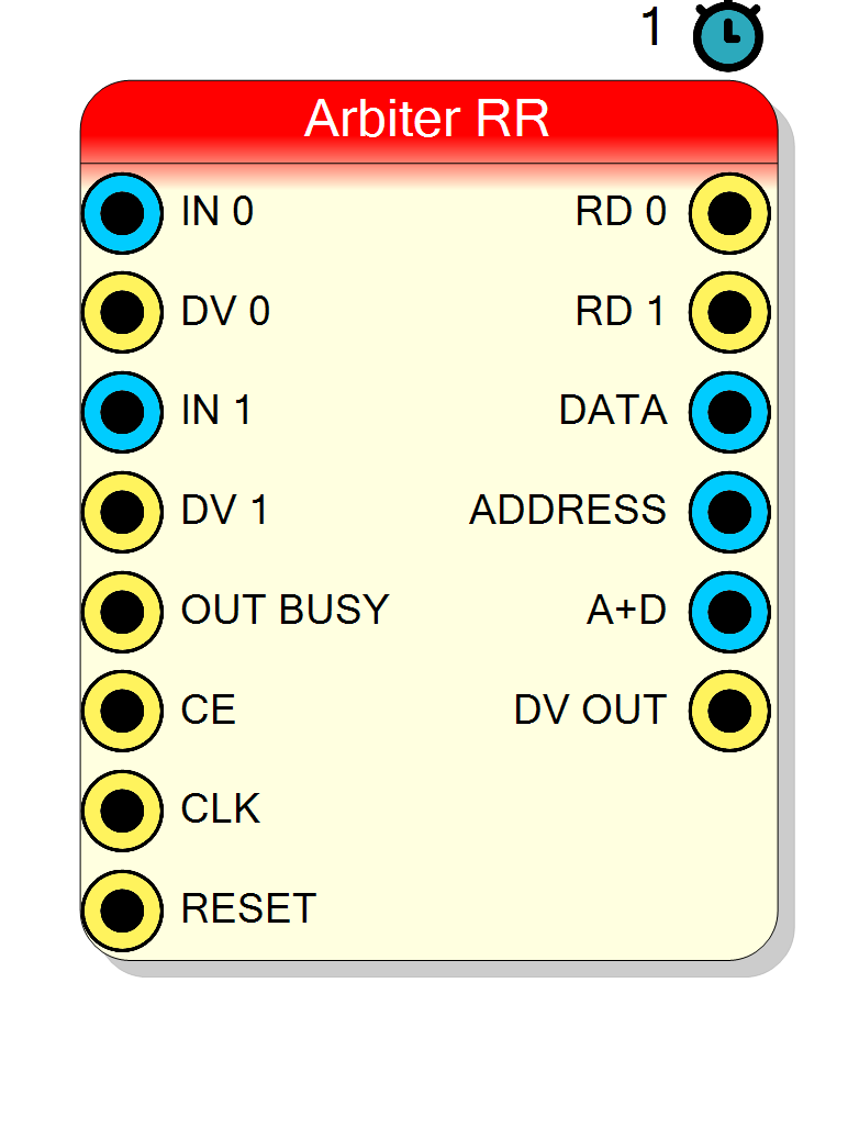
Multiplexes multiple data channels onto a single output using Round Robin arbitration. Essential for routing multiple FIFO sources to a single destination without data loss.
Introduction
The Round Robin Arbiter block implements a fair scheduling algorithm to multiplex multiple input data channels onto a single output. This is a fundamental block in multi-channel DAQ systems where data from multiple sources must be serialized into a single stream (e.g., for transmission to a PC via USB/Ethernet or storage in a shared FIFO).
The arbiter uses time slicing to ensure fair access: each channel is given a maximum number of clock cycles (timeslot) to transfer data before the arbiter moves to the next channel. Channels without data are automatically skipped, ensuring no time is wasted on inactive sources.
Pin Description
Data Valid for channel x.
- HIGH (1): Channel has data available
- LOW (0): Channel is empty/idle Connect to inverted EMPTY signal from source FIFO. On an unserved channel (x >= Served inputs) this pin is never looked at - the channel is not part of the rotation at all.
[ADDRESS (8 bits)] [DATA (N bits)]
Width = 8 + Data Size.
Recommended output for single-wire downstream connection.
Properties
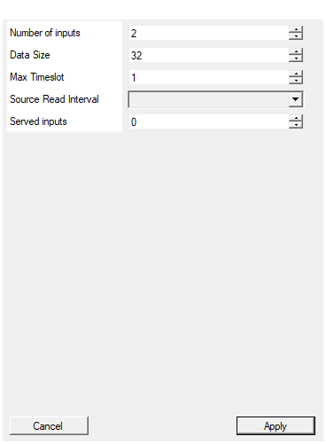
Set the number of input to the arbiter
Number of input channels declared. This is what fixes the pin count and the channel numbering seen on ADDRESS / A+D; it is the count the rest of the design must agree with. Range: 1 to 128, default 2.Default: 2
Range: 1 – 128
Set the number of bits of the input data. Should be common for all inputs
Width of each data channel in bits. Range: 1 to 2048, default 32.Default: 32
Range: 1 – 2048
Specify the number of clock cycles as a timeout for the input before switching to the next channel.
Maximum number of clock cycles per channel before switching. Determines fairness vs. throughput tradeoff. Range: 1 to 65535, default 1.Default: 1
Range: 1 – 65535
Clock cycles delay between one sample and the next one. If set to 0 the arbiter will work in burst mode keeping RD high for all time slot
Clock cycles between consecutive reads from source FIFO.
- 0: Burst mode (RD stays high)
- 1-7: Allows for FIFO read latency Available values: 0, 1, 2, 3, 4, 5, 6, 7, default 1.
Default: 1
Options: 0 1 2 3 4 5 6 7
Number of inputs the arbiter actually serves, out of the declared ‘Number of inputs’. Inputs above this count keep their pins (and therefore the channel numbering on ADDRESS / A+D) but are never polled: their RD output stays at 0 forever and nothing is built for them. Leave it at 0 - or set it to ‘Number of inputs’ or more - to serve every declared input.
Number of declared channels the arbiter actually serves. Channels from this index up keep their pins but are never polled by the round robin rotation, and their RD output stays at 0. 0 (the default) - or any value greater than or equal to InputCount - means “serve them all”, which is exactly the behaviour this block had before the property existed; projects saved earlier read back as 0 and are unaffected. The output format (8 bit ADDRESS,8 + Data Size A+D) never depends on this value.
Range: 0 to 128, default 0.
Default: 0
Range: 0 – 128
Usage
Why Use a Round Robin Arbiter?
In multi-channel DAQ systems, you often have:
- Multiple ADC channels producing data independently
- Multiple processing pipelines generating events
- Multiple detector channels with asynchronous data arrival
All these sources need to send data to a single destination (e.g., a readout FIFO, USB endpoint, or Ethernet buffer). The Round Robin Arbiter solves this problem by:
- Serializing data from N channels onto 1 output
- Identifying each data sample with its source channel (ADDRESS output)
- Preventing starvation by limiting time per channel (timeslot)
- Maximizing throughput by skipping idle channels
The Timeslot Concept
The Max Timeslot parameter defines how many clock cycles a channel can hold the output before the arbiter switches to the next channel.
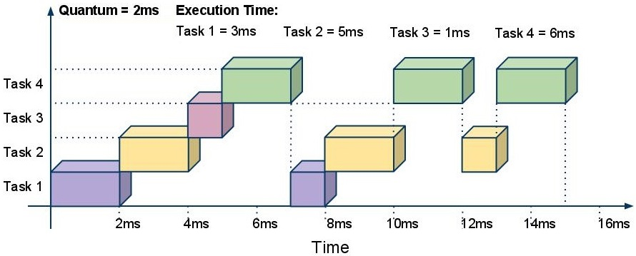
The diagram above illustrates the Round Robin scheduling with time slices. Each task (channel) receives a fixed timeslot. When the timeslot expires or the channel has no more data, the arbiter moves to the next channel in circular order.
When to use short timeslots (1-4):
- Channels produce data at similar, low rates
- You want minimum latency for all channels
- Fairness is critical
When to use long timeslots (10-100+):
- Channels produce bursts of data
- Minimizing channel switching overhead is important
- One channel may have significantly more data than others
Declaring More Inputs Than You Serve (Served inputs)
Number of inputs declares the interface: how many IN/DV/RD pin triplets the block shows, and therefore which channel numbers can appear on ADDRESS / A+D. Served inputs declares the population: how many of those channels the arbiter actually builds logic for.
Leave Served inputs at 0 and everything behaves exactly as before: all declared inputs are served. Set it to a smaller number and the inputs from that index up become unserved:
Served input (i < Served) |
Unserved input (i >= Served) |
|
|---|---|---|
| IN i / DV i pins | present, read | present, ignored - may be left unconnected |
| RD i output | pulses when the channel is read | tied to 0 forever |
| Round robin rotation | polled in turn | never entered - costs no arbitration cycle |
ADDRESS value i |
can be produced | can never be produced |
The unserved inputs still occupy their rows on the block; their captions are marked
(off).
The output format never changes. ADDRESS is always 8 bit and A+D is always
8 + Data Size bits, whatever the declared or served count - a downstream decoder
cannot tell a partial build from a full one by looking at the bus. This is deliberate:
you can raise Served inputs later without re-cutting anything downstream.
Two boundary cases worth knowing:
- Served = 1: the rotation never leaves channel 0. That is the same behaviour as a block declared with a single input - no lock-up, DV OUT keeps flowing, ADDRESS stays 0.
- Served = Number of inputs (or 0): the emitted VHDL is byte for byte the VHDL this block produced before the property existed. Projects saved before it existed read back as 0 and are therefore untouched.
Typical use: keep one design with the maximum channel count (so the channel numbering, the host software and every downstream block stay fixed) and build only the channels a given board population actually has. The unserved channels cost nothing but their pin rows.
Source Read Delay (Read Delay)
The Source Read Interval (read_delay) controls the timing between consecutive reads from a source FIFO:
| Read Delay | Behavior |
|---|---|
| 0 | Burst mode: RD stays HIGH for entire timeslot |
| 1 | One read every 2 clock cycles |
| 2 | One read every 3 clock cycles |
| N | One read every N+1 clock cycles |
This parameter is important when interfacing with FIFOs that have multi-cycle read latency. If your source FIFO has a 2-cycle read latency, set Read Delay = 1 to allow time for data to appear.
Understanding the Output Signals
The arbiter provides three output options for flexibility in downstream processing:
DATA Output
Contains only the data value from the current channel. Use this when:
- You process all channels identically
- Channel identification is not needed downstream
- You want to minimize bus width
ADDRESS Output
Contains the channel number (0 to N-1) encoded as 8 bits. Use this when:
- You need to route data differently based on source
- You’re building a demultiplexer downstream
- You need to log which channel produced each sample
A+D (Address + Data) Output
Combines ADDRESS (8 MSBs) and DATA (remaining bits) into a single bus:
A+D = [ADDRESS (8 bits)] [DATA (N bits)]
MSB LSB
This is the most common output to use because:
- Single connection to downstream FIFO
- Channel information travels with data
- Easy to decode:
channel = A+D[N+7:N],data = A+D[N-1:0]
Interfacing with Source FIFOs
The arbiter is designed to interface with standard FIFOs on the input side:
Source FIFO Arbiter
┌─────────┐ ┌─────────┐
│ DOUT ──┼────────►│ IN x │
│ EMPTY ──┼───(inv)─►│ DV x │ (DV = NOT EMPTY)
│ RD ◄─┼─────────│ RD x │
└─────────┘ └─────────┘
- Connect FIFO’s DOUT to arbiter’s IN
- Connect inverted FIFO’s EMPTY to arbiter’s DV (DV=1 means data available)
- Connect arbiter’s RD to FIFO’s RD (read enable)
Backpressure Handling (OUT BUSY)
The OUT BUSY input allows the downstream block to pause the arbiter:
- When OUT BUSY = 1, the arbiter freezes and holds its current state
- When OUT BUSY = 0, normal operation resumes
Connect this to the FULL signal of a downstream FIFO to prevent data loss when the output buffer is full.
State Machine Operation
The arbiter operates with a simple state machine:
- s0 (Check): Check if current channel has data (DV=1)
- If yes: Assert RD, go to s0b (wait) or s1 (output)
- If no: Move to next channel
- s0b (Wait): Wait for read_delay cycles (FIFO latency)
- s1 (Output): Output data, check for timeout or empty
- If timeout or empty: Move to next channel
- Otherwise: Continue reading
Timing Diagram
In questo esempio:
- Il canale 0 ha dati (DV_0=1), l’arbiter legge 3 sample (D0, D1, D2)
- Il timeslot scade, passa al canale 1
- Il canale 1 ha dati (DV_1=1), l’arbiter legge D3, D4…
Resources & Timing
-
Latency: 2-3 clock cycles (depending on Read Delay)
-
Throughput: 1 sample per (ReadDelay + 1) clock cycles per active channel
Minimal logic resources. No BRAM required. An unserved input (see Served inputs) costs no rotation cycle and no logic, only its pin rows.