
Float Clamp
Returns the selected IEEE-754 floating point VALUE, not a boolean flag. Needs no floating point IP and no DSP: the ordering of IEEE-754 numbers matches the ordering of their bit patterns once mapped through a monotonic key, so a single integer comparator does the whole job.
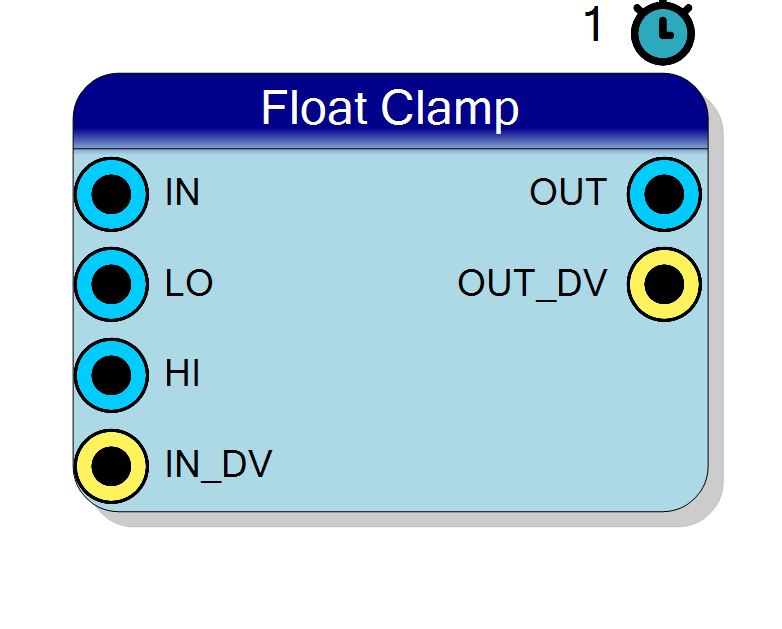
Introduction
The block computes
$$ \mathrm{OUT} = \min\bigl(\max(\mathrm{IN}, \mathrm{LO}), \mathrm{HI}\bigr) $$
and outputs the selected value. This is the difference with the boolean comparator blocks (Equal, Greater, Smaller, …), which only report the outcome of the test on a 1-bit flag: here the winning operand itself comes out.
The integer counterpart of this block is Limit, already in this plugin.
All ports are IEEE-754 numbers, single (32 bit) or double (64 bit) precision, selected by the FloatType property.
Pin Description
Properties
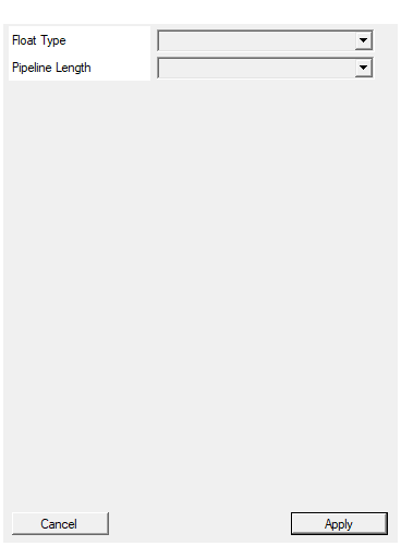
IEEE-754 precision of every port: Single (32 bit) or Double (64 bit).
IEEE-754 precision used by every port:
- Single – 32 bit (1 sign, 8 exponent, 23 mantissa)
- Double – 64 bit (1 sign, 11 exponent, 52 mantissa)
Default: Single
Options: Single Double
Number of output register stages, i.e. the latency in clock cycles. 0 makes the block purely combinational.
Number of output register stages, i.e. latency in clock cycles (0 to 8). 0 makes the block purely combinational. Does not affect the result.Default: 1
Options: 0 1 2 3 4 5 6 7 8
Functional description
$$ \mathrm{OUT} = \min\bigl(\max(\mathrm{IN}, \mathrm{LO}), \mathrm{HI}\bigr) $$
where
IN– IEEE-754 input operandLO– IEEE-754 input operandHI– IEEE-754 input operandOUT– the selected operand, same format as the inputs
If LO is greater than HI the upper bound wins, because the lower bound is
applied first and the upper bound second.
How the comparison is done
IEEE-754 was designed so that, within one sign, the ordering of the numbers is the same as the ordering of their raw bit patterns read as integers. Mapping the pattern through
$$ \mathrm{key}(x) = \begin{cases} \lnot x & \text{sign bit set}\ x \lor 2^{W-1} & \text{otherwise} \end{cases} $$
extends that property across the sign, so ONE unsigned integer comparison orders any two floats exactly. The block therefore costs a comparator and a multiplexer: no floating point IP, no DSP slice and no multi-cycle FPU latency.
Special values
- NaN – follows the IEEE-754
minNum/maxNumconvention: a NaN operand is ignored and the other one is returned. For Clamp, a NaN bound is ignored, while a NaN onINpasses through unchanged. - Infinities – ordered normally, so $-\infty$ is the smallest value and $+\infty$ the largest.
- Signed zeros – ordered $-0 < +0$, so Min returns $-0$ and Max returns $+0$. The two are numerically equal; this is only a deterministic tie break.
Implementation
Plain VHDL (Resources/Code/float_minmax.vhd), shared with the other operations of
the same kind through the OP generic – the same way comparator.vhd already backs
Equal, Greater and Smaller. No HLS is involved, so this block builds without Vitis
HLS installed, and it uses no DSP slice.
Latency
PipelineLength sets the number of output register stages, i.e. the latency in clock cycles. Set it to 0 for a purely combinational block; raise it to help timing closure at high clock rates. It never changes the result.
Typical use cases
- Protecting a downstream stage from out-of-range values
- Programmable limiter with run-time thresholds
- Enforcing a physical range on a computed quantity