
Timer (Enable)
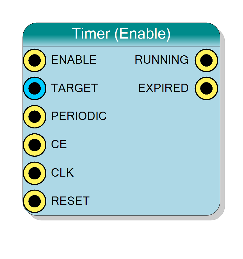
Programmable timer that generates periodic pulses or one-shot events based on a configurable target count. Counts clock cycles while enabled and asserts EXPIRED output when target is reached. Supports both periodic and one-shot modes. Configurable counter width from 8 to 64 bits.
Introduction
This block implements a programmable countdown timer that generates pulses after a specified time delay. Unlike chronometers that measure elapsed time, timers generate time-based events when a target count is reached.
Key features:
- Programmable timeout period via TARGET input
- Periodic or one-shot operation modes
- EXPIRED output pulses when timer reaches target
- Enable-controlled counting
- Configurable counter width (8-64 bits)
Operation:
- Load target count via TARGET input
- Assert ENABLE=‘1’ to start counting
- Counter increments each clock cycle
- When count reaches TARGET, EXPIRED pulses high
- In periodic mode, automatically restarts; in one-shot mode, stops
$$ \text{Timeout Period (seconds)} = \frac{\mathrm{TARGET}}{\text{CLK Frequency (Hz)}} $$
Pin Description
Enable input - controls timer operation.
- ‘1’ = Timer enabled, counting active
- ‘0’ = Timer disabled, counter holds value
In One-Shot mode: Transitioning ENABLE from ‘0’ to ‘1’ restarts the timer from 0.
In Periodic mode: Keeps timer running continuously.
Target count input (unsigned integer).
Specifies the count value at which EXPIRED is asserted.
Width: Matches Bit Number property
Dynamic update: Can be changed while timer is running. New value takes effect immediately, but may cause unexpected behavior if changed mid-count.
Calculation: TARGET = (Desired_Time × CLK_Freq) - 1
For precise timing, keep TARGET constant during operation.
Periodic mode control.
- ‘1’ = Periodic mode: Auto-restart on expiration
- ‘0’ = One-shot mode: Stop counting on expiration
Periodic mode: Counter resets to 0 when TARGET reached, EXPIRED pulses for one cycle, counting continues.
One-shot mode: Counter stops at TARGET, EXPIRED stays high until ENABLE=‘0’.
Can be changed dynamically to switch between modes.
Clock enable input (active high).
Global clock enable. When CE=‘0’, counting is suspended regardless of ENABLE state.
Typically tied to ‘1’ for normal operation.
Default: Connects to ‘1’ if left unconnected.
Clock input.
Counter increments on rising edge when ENABLE=‘1’ and CE=‘1’.
Timer resolution = 1 / CLK_Frequency
Default: Connects to global clock if left unconnected.
Synchronous reset input (active high).
- ‘1’ = Reset counter to 0, clear EXPIRED
- ‘0’ = Normal operation
Resets timer regardless of ENABLE state.
Default: Connects to global reset if left unconnected.
Running status output.
- ‘1’ = Timer is actively counting (ENABLE=‘1’ and not expired in one-shot mode)
- ‘0’ = Timer is idle or expired
Periodic mode: Tracks ENABLE input One-shot mode: Clears when TARGET reached
Registered output.
Expiration flag output.
Periodic mode:
- Pulses high for one clock cycle when COUNT=TARGET
- Returns to ‘0’ on next cycle as counter resets
One-shot mode:
- Goes high when COUNT=TARGET
- Stays high until ENABLE=‘0’
This output can be used for:
- Interrupt generation
- Event triggering
- Timing validation
Registered output, synchronous to CLK.
Properties
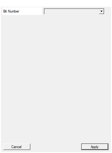
Set the number of bit used in the timer accumulator
Number of bits in the timer counter.
Available values: 8, 16, 24, 32, 40, 48, 56, 64
Determines:
- Maximum TARGET value = 2^BitNumber - 1
- Maximum timeout period = (2^BitNumber - 1) / CLK_Frequency
- WIDTH of TARGET input
Choose the smallest value that accommodates your maximum required timeout to minimize resource usage.
Default: 32
Options: 8 16 24 32 40 48 56 64
Functional description
The timer implements an up-counter that compares against a programmable target value:
$$ \mathrm{COUNT}(n+1) = \begin{cases} 0 & \text{if COUNT=TARGET (and PERIODIC=‘1’)} \ \mathrm{COUNT}(n) + 1 & \text{if ENABLE=‘1’ and CE=‘1’ and COUNT<TARGET} \ \mathrm{COUNT}(n) & \text{otherwise} \end{cases} $$
$$ \mathrm{EXPIRED}(n) = \begin{cases} 1 & \text{if COUNT(n)=TARGET} \ 0 & \text{otherwise} \end{cases} $$
Operating modes
Periodic Mode (PERIODIC=‘1’):
- Counter automatically resets to 0 when TARGET is reached
- EXPIRED pulses high for one clock cycle
- Counting resumes immediately
- Generates continuous periodic pulses
- Period = (TARGET + 1) clock cycles
One-Shot Mode (PERIODIC=‘0’):
- Counter stops when TARGET is reached
- EXPIRED stays high until ENABLE=‘0’
- Requires ENABLE=‘0’ then ‘1’ to restart
- Generates single timeout event
Time calculation
For a given timeout period:
$$ \mathrm{TARGET} = \text{Desired Time (s)} \times \text{CLK Frequency (Hz)} - 1 $$
Examples @ 100 MHz clock:
- 1 µs delay: TARGET = 100 - 1 = 99
- 1 ms delay: TARGET = 100,000 - 1 = 99,999
- 1 s delay: TARGET = 100,000,000 - 1 = 99,999,999
Maximum timeout period
With N-bit counter:
- Maximum TARGET = 2^N - 1
- Maximum timeout = (2^N - 1) / CLK_Frequency seconds
Timing diagrams
Periodic mode
Periodic mode shows:
- Counter counts 0→1→2→3 repeatedly
- EXPIRED pulses when COUNT=TARGET (3)
- Counter auto-resets to 0
- Period = 4 clock cycles (TARGET+1)
One-shot mode
One-shot mode shows:
- Counter counts to TARGET (3) and stops
- EXPIRED remains high until ENABLE=‘0’
- Counter holds value until reset by ENABLE=‘0’
- Requires ENABLE toggle to restart
Typical use cases
- Timeout generation: Watchdog timers, communication timeouts
- Periodic interrupts: Generate regular CPU interrupts or sampling triggers
- Delay generation: Create precise time delays in state machines
- Pulse generation: Generate pulses at specific intervals
- Sampling clock: Create slower sampling clocks from system clock
- Debouncing: Time-based input signal debouncing
- Protocol timing: Generate protocol-specific timing (e.g., I2C delays)
Design considerations
Periodic vs One-Shot selection
Use Periodic Mode for:
- Regular interrupts or triggers
- Clock division / frequency generation
- Periodic sampling or polling
- Continuous event generation
Use One-Shot Mode for:
- Timeout detection
- Single-event delays
- Watchdog timers
- Pulse width generation
Target value constraints
- TARGET must be < 2^BitNumber
- Minimum useful TARGET = 0 (1 clock cycle period)
- Maximum TARGET = 2^BitNumber - 1
- TARGET can be changed dynamically while running (takes effect on next cycle)
Choosing bit width
Select based on maximum timeout needed:
| Bit Width | Max TARGET | @ 100 MHz Max Timeout | @ 200 MHz Max Timeout |
|---|---|---|---|
| 8 bits | 255 | 2.55 µs | 1.28 µs |
| 16 bits | 65,535 | 655 µs | 328 µs |
| 24 bits | 16,777,215 | 168 ms | 84 ms |
| 32 bits | 4,294,967,295 | 42.9 s | 21.5 s |
Resource usage
- One N-bit counter
- One N-bit comparator
- Small control logic for periodic/one-shot modes
- Minimal FPGA resources