
Bessel (IIR-I)
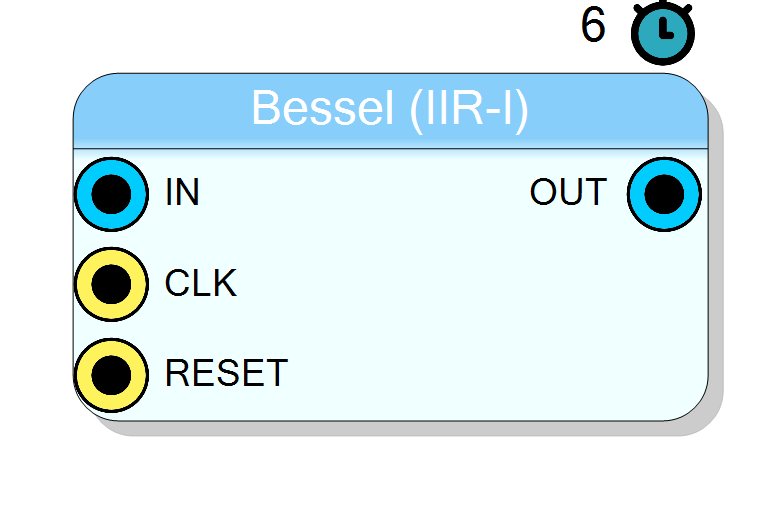
First-order IIR Bessel filter with automatic coefficient calculation. Implements low-pass or high-pass filtering with maximally flat group delay for signal conditioning.
Introduction
The Bessel (IIR-I) block implements a first-order IIR (Infinite Impulse Response) filter operating in real-time in FPGA.
The component includes automatic filter coefficient calculation based on filter type (low/high pass) and cutoff frequency.
Bessel filters have a maximally flat group delay (maximally linear phase response), which preserves the wave shape of filtered signals in the passband. This makes them ideal for pulse processing applications where waveform fidelity is important.
The filter is named after German mathematician Friedrich Bessel (1784-1846). The filters are also called Bessel-Thomson filters in recognition of W. E. Thomson, who developed the filter design method in 1949.
Pin Description
Input signal. Fixed-point number input. Size depends on Input Data Type property:
- UINT16: 16-bit unsigned
- INT17: 17-bit signed
Filtered output signal. Fixed-point number output with same size as input. Size depends on Input Data Type property:
- UINT16: 16-bit unsigned
- INT17: 17-bit signed
Properties
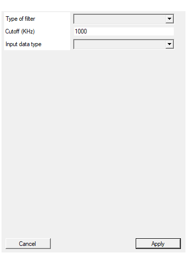
Select between low pass and high pass filter
Filter type selection.
- Low Pass: Attenuates frequencies above the cutoff
- High Pass: Attenuates frequencies below the cutoff Available values: Low Pass, High Pass, default Low Pass.
Default: Low Pass
Options: Low Pass High Pass
Set the filter pole/zero position according to the selected bandwidth in KHz
Filter cutoff frequency in kHz. The -3dB point of the filter response. Valid range: 10 - 40000 kHz, default 1000 kHz.Default: 1000
Select input data type
Input/output data type selection.
- UINT16: 16-bit unsigned integer (0 to 65535)
- INT17: 17-bit signed integer (-65536 to 65535) Available values: UINT16, INT17, default UINT16.
Default: UINT16
Options: UINT16 INT17
Usage
Bessel Filter Characteristics
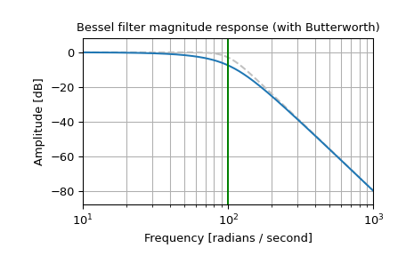
The Bessel filter has several important properties:
- Maximally flat group delay: Preserves pulse shapes in the passband
- Minimal overshoot: Less than other common filters like Butterworth
- Gaussian-like impulse response: Approaches Gaussian shape as order increases
- Better shaping factor: Compared to Gaussian filters of the same order
Digital Implementation Note
The Bessel filter is inherently an analog filter. This implementation generates digital Bessel filters using the bilinear transform, which does not perfectly preserve the phase response of the analog filter.
The approximation is accurate at frequencies below about fs/4 (quarter of sampling frequency). For maximally-flat group delay at higher frequencies, phase-preserving transformation techniques would be required.
IIR Filter Basics
An IIR filter uses both current/past input samples and past output samples to calculate the current output. This recursive structure gives the “Infinite Impulse Response” name because the response to a single input impulse can theoretically continue indefinitely.
Standard first-order IIR transfer function:
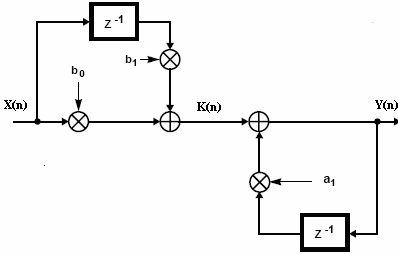
$$ y[n] = b_0 x[n] + b_1 x[n-1] - a_1 y[n-1] $$
Standard IIR implementation:
python
for j in range(2, len(x)):
y[j] = b_z[0]*x[j] + b_z[1]*x[j-1] - a_z[1]*y[j-1]
Clustered Lookahead Technique
The main challenge with IIR filters is that their recursive nature introduces computational delay due to sequential processing. This block uses the Clustered Lookahead technique to enable parallel processing and reduce latency.
The technique involves:
- Clustering: Dividing the filter into smaller sub-filters that operate on portions of the overall response
- Lookahead: Pre-calculating future filter outputs to enable parallel processing
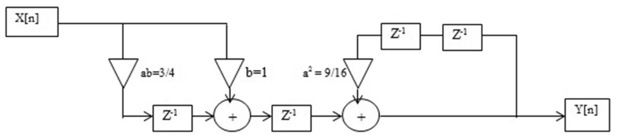
This transforms the filter from sequential to parallel processing, significantly reducing computational delay while maintaining filter accuracy.
Reference: A universal look-ahead algorithm for pipelining IIR filters
Hardware Implementation
The implemented clustered filter uses the following transfer function:
$$ y[j] = b’_0 x[j] + b’_1 x[j-1] + b’_2 x[j-2] + b’_3 x[j-3] - a’_3 y[j-3] $$
Clustered IIR implementation:
python
for j in range(3, len(x)):
y[j] = bq[0]*x[j] + bq[1]*x[j-1] + bq[2]*x[j-2] + bq[3]*x[j-3] - aq[1]*y[j-3]
Coefficient Calculation
SciCompiler automatically calculates the filter coefficients using an internal Python-based filter calculator. The algorithm transforms standard Bessel coefficients into clustered lookahead coefficients.
Reference algorithm for offline simulation:
python
import numpy as np
from scipy import signal
N = 1 # Filter order
fs = 250e6 # Sampling frequency (Hz)
fc = 0.2e6 # Cutoff frequency (Hz)
Wn = fc / (fs / 2) # Normalized frequency
# Get standard Bessel coefficients
b_z, a_z = signal.bessel(N, Wn, btype='low') # or 'high'
# Transform to clustered lookahead coefficients
an = [1, a_z[1]**3]
bn = [1, -a_z[1], a_z[1]**2]
bq = np.convolve(bn, b_z)
aq = an
Resource Usage
| Parameter | Value |
|---|---|
| Latency | 6 clock cycles |
| DSP Usage | 5 DSP slices |
| Throughput | 1 sample per clock cycle |
Typical Applications
- Anti-aliasing filters
- Pulse shaping for spectroscopy
- Signal conditioning with minimal waveform distortion
- Noise reduction while preserving pulse timing
- Pre-filtering for trigger circuits