
User LED
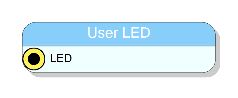
Board pin block that drives the DT5550 user LED from the diagram. One 1-bit input, one concurrent assignment to the top-level LED_USER port, no logic and no register. Zero latency; whatever you wire in is what the pin shows.
Introduction
Principle of Operation
User LED is the simplest of the Board Pin blocks: a single bit of your design wired straight to the DT5550’s user-controllable LED.
There is no blinker, no pulse stretcher and no register inside the block. If you want the LED to blink, to latch an error or to be visible at all for a one-clock event, build that in the diagram and feed the result here - a pulse one clock wide at 80 MHz is 12.5 ns and no eye will see it.
Pin Description
LED state. Bit 0 of this 1-bit vector is assigned directly to the
LED_USER top-level port.
The assignment is emitted unconditionally (there is no open guard on
this pad), so wire it. Level-sensitive, not edge-sensitive: the LED
follows the signal for exactly as long as it is asserted.
Properties
⚙️ Detailed Operation
What the block compiles to
CompileHDL adds one 1-bit input pad LED and emits exactly one line:
LED_USER <= <your signal>(0);
That is all. No process, no generic, no compiler message, no register map entry.
The board side
LED_USER is a top-level output port of the DT5550 design, declared
unconditionally by the board template (dt5550b_top.vht):
LED_USER : out std_logic
and constrained by the board’s XDC to
tcl
set_property PACKAGE_PIN J19 [get_ports LED_USER]
set_property IOSTANDARD LVCMOS25 [get_ports LED_USER]
Nothing else in the template or in the board plug-in assigns LED_USER, so
this block is its only driver. In a design that does not contain the
block, the port is left undriven.
Polarity
The bit is passed through with no inversion and no buffering - the
generated line is a direct assignment. Whether a '1' lights the LED or
extinguishes it depends on how the LED is wired on the board, which is
not determined from these sources. If it comes out the wrong way round,
invert the signal in the diagram.
Timing
Pure wiring: zero latency, no clock, no reset. There is also no glitch filtering - combinational hazards on the driving signal reach the pin.
Typical use
- “Firmware alive” heartbeat, driven by the MSB of a free-running counter.
- Sticky error flag, driven by a set-only flip-flop in the diagram.
- Acquisition-running indicator, driven by a DAQ block’s
BUSYoutput.
Board availability
Offered only on the DT5550 (board plug-in GUID
413F904B-7FD0-43EF-B127-74278C23F1A5).
SupportedBoard also lists DT5550SE and DT5560, but neither has any
effect: the toolbox visibility filter in Form1_plugins.vb implements a
BOARD_MODELS.DT5550 branch only, no board plug-in declares itself
DT5550SE, and the DT5560 top-level template contains no LED_USER port.