
Oscilloscope
Multi-channel oscilloscope IP core for Xilinx-7 devices with up to 32 analog input channels plus 4 digital lines per channel. Supports configurable word size (16/24/28/32 bits), programmable decimation, and multiple trigger sources (external, analog, digital, software). Data is stored in a circular buffer with configurable pre-trigger depth.
Introduction
Principle of Operation
The Oscilloscope block captures waveform data from multiple analog and digital inputs into a circular buffer. When a trigger condition is met, the acquisition continues for a programmable post-trigger period, then data becomes available for readout.
Let:
- $f_s$ = input sampling frequency (clock rate)
- $D = \text{CONFIG_DECIMATOR}$, $N = 2^D$ (decimation ratio)
- $S$ = number of samples per channel (buffer size)
- $P$ = pre-trigger samples (
CONFIG_PRETRIGGER)
When $D = 0$ there is no decimation and every sample is stored. When $D > 0$ the core keeps one sample every $N$ input cycles:
$$ f_{effective} = \frac{f_s}{2^D} $$
The oscilloscope can be visualized through the Resource Explorer Oscilloscope tool, or read programmatically using the SciSDK library.
SciSDK Documentation: https://nuclearinstruments.github.io/SCISDK/
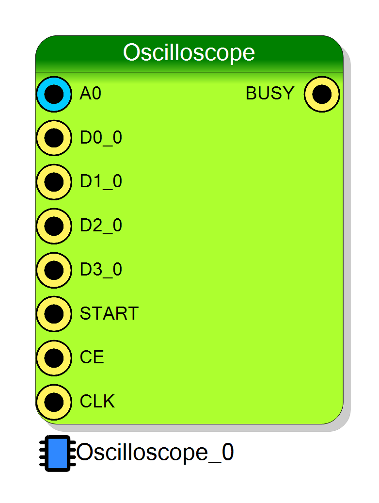
Pin Description
000).
Properties
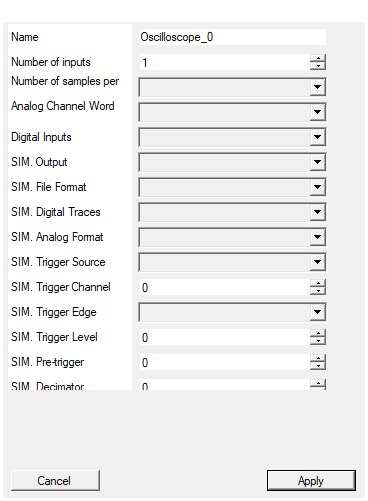
Set the name of the endpoint
Logical endpoint name used in register map. Used in Resource Explorer and SciSDK. Default: Oscilloscope_0Default: Oscilloscope_0
Set the number of input to the virtual block
Number of analog input channels (1-32). Each channel has one analog input plus 4 optional digital inputs. Default: 1Default: 1
Range: 1 – 32
Set the number of samples stored for each acquisition
Buffer length per channel in samples. Available values: 128, 256, 512, 1024, 2048, 4096, 8192, 16384, 32768, 65536, 131072. Default: 1024Default: 1024
Options: 128 256 512 1024 2048 4096 8192 16384 32768 65536 131072
Set the analog channel word size in bits
Analog channel word size in bits. Available values: 16, 24, 28, 32. Default: 16Default: 16
Options: 16 24 28 32
Enable/Disable Digital Inputs
Enable or disable the 4 digital inputs per channel. Options: Enabled, Disabled. Default: EnabledDefault: Enabled
Options: Enabled Disabled
What the block writes to disk WHEN THE PROJECT IS SIMULATED (no effect on the synthesized design). None: the block does nothing, as it has always done. Single file: every captured waveform goes into one file. Multi file per channel: one file per analog channel (and its digital lines). Multi file per event: one file per trigger. The files are written in the sim_results folder of the project, named after
What the block writes to disk when the project is simulated. It has no effect on the synthesized design.
| Value | Effect |
|---|---|
| None | Nothing is written (default). |
| Single file | Every captured waveform goes into one file. |
| Multi file per channel | One file per analog channel, with its digital lines. |
| Multi file per event | One file per trigger. |
Files are written to the project’s sim_results folder, named after
<page>_<endpoint> (<endpoint> on the top page) plus _ch<n> / _ev<n> in the
multi-file modes. The exact paths are printed in the compiler log.
Default: None
Default: None
Options: None Single file Multi file per channel Multi file per event
Layout of the simulation output files. The first column is always the timestamp, in ns, of the trigger that captured the waveform. One sample per row: ‘<time_ns>
Layout of the simulation output files. The first column is always the timestamp, in ns, of the trigger that captured the waveform.
- One sample per row —
<time_ns> <A0> <A1> ... <D0_0> <D1_0> ...: one row per acquired sample, one column per analog channel and per digital trace. - One waveform per row —
<time_ns> <trace> <s0> <s1> ... <sN-1>: the whole waveform of one trace on a single row, the trace name in the second column.
Default: One sample per row
Default: One sample per row
Options: One sample per row One waveform per row
Whether the 4 digital lines of each channel are written to the simulation files alongside the analog trace. Disable it to get analog-only files, which are much smaller and easier to plot. It has no effect when the block’s Digital Inputs are disabled: there is nothing to write.
Whether the 4 digital lines of each channel are written to the simulation files alongside the analog trace.
Turn it off for analog-only files — much smaller, and easier to feed to a plotting tool. It has no effect when the block’s DigitalIn property is Disabled: there is nothing to write in the first place.
Default: Enabled
Default: Enabled
Options: Enabled Disabled
How an analog sample is interpreted, both when it is written to the file and when it is compared against the simulation trigger level. Unsigned reproduces the hardware exactly (the real block compares the raw port as unsigned). Choose Signed when the input carries two’s complement data and you want a plottable trace. An unsigned 32 bit sample has no VHDL integer representation and is written as signed.
How an analog sample is interpreted, both when written to the file and when compared against the simulation trigger level.
Unsigned reproduces the hardware exactly — the real block compares the raw port
with STD_LOGIC_UNSIGNED. Pick Signed when the input carries two’s complement
data and you want a directly plottable trace; the trigger level is then read as
signed too, so the two stay consistent.
An unsigned 32-bit sample has no VHDL integer representation and is written as signed.
Default: Unsigned
Default: Unsigned
Options: Unsigned Signed
Trigger source used during the simulation. It replaces CONFIG_TRIGGER_MODE. External: the START pin. Analog threshold: the level crossing on the selected channel. Free run: capture continuously. Digital D0..D3: the selected digital line of the selected channel. The scope arms itself at reset and re-arms after every capture, since no software can arm it in a simulation.
Trigger source used during the simulation; it replaces CONFIG_TRIGGER_MODE.
Options: External (START pin), Analog threshold, Free run,
Digital D0, Digital D1, Digital D2, Digital D3.
The scope arms itself at reset and re-arms after every capture, because no software
can write CONFIG_ARM in a simulation.
Default: Analog threshold
Default: Analog threshold
Options: External (START pin) Analog threshold Free run Digital D0 Digital D1 Digital D2 Digital D3
Channel the simulation trigger looks at. Used by the analog threshold and by the digital D0..D3 sources; ignored by the others. Clamped to the number of inputs at compile time.
Channel the simulation trigger looks at. Used by the analog threshold and by the digital sources, ignored by the others. Clamped to the number of inputs at compile time, with a warning. Default: 0Default: 0
Range: 0 – 31
Edge of the analog threshold trigger. Rising fires when the sample crosses the level upwards, Falling when it crosses it downwards. Ignored by the other trigger sources.
Edge of the analog threshold trigger: Rising fires when the sample crosses the level upwards, Falling downwards. Ignored by the other sources. Default: RisingDefault: Rising
Options: Rising Falling
Threshold of the analog trigger, in raw ADC counts, read with the SIM. Analog Format interpretation. It replaces CONFIG_TRIGGER_LEVEL.
Threshold of the analog trigger in raw ADC counts, read with the SIM. Analog Format interpretation. ReplacesCONFIG_TRIGGER_LEVEL.
Default: 0
Default: 0
Number of samples kept before the trigger, exactly like CONFIG_PRETRIGGER. Must be smaller than the number of samples per channel; it is clamped at compile time.
Number of samples kept before the trigger, exactly likeCONFIG_PRETRIGGER. Must be
smaller than Samples; clamped at compile time with a warning.
Default: 0
Default: 0
Decimation used during the simulation, same meaning as CONFIG_DECIMATOR: 0 keeps every sample, 1 keeps one out of two, N keeps one out of N+1. The digital lines are OR-accumulated over the discarded samples and the trigger is held, exactly as the hardware does, so a pulse shorter than the decimation window is not lost.
Decimation used during the simulation, same meaning as CONFIG_DECIMATOR: 0 keeps
every sample, 1 keeps one out of two, N keeps one out of N+1.
As in hardware, the digital lines are OR-accumulated over the discarded samples and the trigger is held across the decimation window, so a pulse shorter than the window is not lost. Default: 0
Default: 0
Stop capturing after this many waveforms. The scope free-runs in simulation, so this is what keeps a long run from producing a huge file - or, in ‘Multi file per event’ mode, a huge number of files. 0 means no limit.
Stop capturing after this many waveforms. The scope free-runs in simulation, so this is what keeps a long run from producing a huge file — or, in Multi file per event mode, a huge number of files. 0 means no limit. Default: 64Default: 64
⚙️ Detailed Operation
Trigger Flow
- ARM (
CONFIG_ARM0→1) arms the capture engine and clears internal counters - Continuous Sampling writes into a circular buffer
- Trigger Evaluation each cycle (external START, analog threshold, software, or digital line)
- Trigger Latch stores the write pointer as trigger position (
READ_POSITION) - Post-Trigger Collection continues until total programmed samples are filled
- Ready:
READ_STATUS = 1, acquisition halts (buffer frozen for readout)
Circular Buffer and Data Reordering
The data is stored in a circular buffer. After readout, it must be reordered so that the trigger sample appears at the pre-trigger position:
Reordering Algorithm:
c
position = read_register(READ_POSITION);
fix_position = position - pre_trigger;
if (fix_position >= 0) {
// Trigger after pre-trigger position
reordered = data[fix_position:] + data[:fix_position];
} else {
// Trigger before pre-trigger position
idx = fix_position + nsamples;
reordered = data[idx:] + data[:idx];
}
Word Layout
Each 32-bit word contains one analog sample plus 4 digital bits:
16-bit analog mode:
[15:0] = Analog sample (16-bit signed)
[16] = Digital 0
[17] = Digital 1
[18] = Digital 2
[19] = Digital 3
[31:20] = Reserved
Decoding (16-bit mode):
c
int16_t analog = (int16_t)(word & 0xFFFF);
uint8_t d0 = (word >> 16) & 1;
uint8_t d1 = (word >> 17) & 1;
uint8_t d2 = (word >> 18) & 1;
uint8_t d3 = (word >> 19) & 1;
Timing Calculations
| Item | Formula |
|---|---|
| Effective sample rate | $f_{eff} = f_s / 2^D$ |
| Time between samples | $\Delta t = 2^D / f_s$ |
| Pre-trigger duration | $T_{pre} = P \cdot 2^D / f_s$ |
| Post-trigger duration | $T_{post} = (S-P) \cdot 2^D / f_s$ |
| Total acquisition time | $T_{total} = S \cdot 2^D / f_s$ |
Configuration Registers
CONFIG_ARM
Rising edge (0→1) arms acquisition. Write 0 then 1 to re-arm.
CONFIG_DECIMATOR
Decimation exponent $D$ (0 = no decimation, effective rate = $f_s / 2^D$).
CONFIG_TRIGGER_MODE
Trigger configuration bit field:
| Bits | Purpose | Values |
|---|---|---|
| 2:0 | Trigger Source | 000 external, 001 analog, 010 software, 100-111 digital D0-D3 |
| 3 | Trigger Edge (analog) | 0 rising, 1 falling |
| 6 | Software Trigger | Set 1 to trigger immediately (with source = 010) |
| 15:8 | Channel Selection | Channel index for analog/digital trigger |
CONFIG_PRETRIGGER
Number $P$ of samples before trigger in the output buffer.
CONFIG_TRIGGER_LEVEL
Threshold (LSB) for analog trigger comparator.
READ_STATUS
Acquisition status: 0 = not ready, 1 = data ready for readout.
READ_POSITION
Index of the trigger sample in the circular buffer.
Software Integration with SciSDK
The Oscilloscope is fully supported by SciSDK. For complete documentation see: SciSDK Oscilloscope Guide
Trigger Modes
| Mode | Description |
|---|---|
disabled |
Free-running, no trigger |
self |
Software trigger (immediate) |
analog |
Analog threshold crossing |
ext |
External START input |
digital |
Digital input transition |
Available Parameters
| Parameter | Access | Description | Default |
|---|---|---|---|
decimator |
R/W | Decimation exponent $D$ | 0 |
pretrigger |
R/W | Pre-trigger samples | 150 |
trigger_level |
R/W | Analog trigger threshold (LSB) | 2000 |
trigger_channel |
R/W | Channel for analog/digital trigger | 0 |
trigger_mode |
R/W | disabled, self, analog, ext, digital |
ext |
trigger_polarity |
R/W | pos (rising) or neg (falling) |
pos |
acq_mode |
R/W | blocking or non-blocking |
blocking |
timeout |
R/W | Timeout in ms for blocking mode | 100 |
data_processing |
R/W | raw or decoded |
decoded |
Available Commands
| Command | Description |
|---|---|
arm |
Arm the oscilloscope (same as CONFIG_ARM 0→1) |
reset_read_valid_flag |
Clear the data ready flag |
C/C++ Example
c
#include "SciSDK_DLL.h"
// Allocate decoded buffer
SCISDK_OSCILLOSCOPE_DECODED_BUFFER *buffer;
SCISDK_AllocateBuffer("board0:/MMCComponents/Oscilloscope_0",
T_BUFFER_TYPE_DECODED,
(void**)&buffer, _sdk);
// Configure
SCISDK_SetParameterString("board0:/MMCComponents/Oscilloscope_0.trigger_mode",
"analog", _sdk);
SCISDK_SetParameterInteger("board0:/MMCComponents/Oscilloscope_0.trigger_level",
5000, _sdk);
SCISDK_SetParameterInteger("board0:/MMCComponents/Oscilloscope_0.pretrigger",
200, _sdk);
SCISDK_SetParameterInteger("board0:/MMCComponents/Oscilloscope_0.decimator",
0, _sdk);
SCISDK_SetParameterString("board0:/MMCComponents/Oscilloscope_0.acq_mode",
"blocking", _sdk);
SCISDK_SetParameterString("board0:/MMCComponents/Oscilloscope_0.data_processing",
"decoded", _sdk);
// Arm and read
SCISDK_ExecuteCommand("board0:/MMCComponents/Oscilloscope_0.arm", "", _sdk);
int ret = SCISDK_ReadData("board0:/MMCComponents/Oscilloscope_0",
(void*)buffer, _sdk);
if (ret == NI_OK) {
// Access analog data (already reordered)
for (int i = 0; i < buffer->info.samples_analog; i++) {
int32_t sample = buffer->analog[i];
printf("Sample %d: %d\n", i, sample);
}
// Access digital data
for (int i = 0; i < buffer->info.samples_digital; i++) {
uint8_t d0 = buffer->digital[i * 4 + 0];
uint8_t d1 = buffer->digital[i * 4 + 1];
uint8_t d2 = buffer->digital[i * 4 + 2];
uint8_t d3 = buffer->digital[i * 4 + 3];
}
printf("Trigger position: %d\n", buffer->info.trigger_position);
}
// Free buffer
SCISDK_FreeBuffer("board0:/MMCComponents/Oscilloscope_0",
T_BUFFER_TYPE_DECODED, (void**)&buffer, _sdk);
Python Example
python
from scisdk.scisdk import SciSDK
import matplotlib.pyplot as plt
sdk = SciSDK()
sdk.AddNewDevice("usb:10500", "dt5560", "board0", "RegisterFile.json")
# Allocate buffer
res, buf = sdk.AllocateBuffer("board0:/MMCComponents/Oscilloscope_0",
sdk.T_BUFFER_TYPE_DECODED)
# Configure
sdk.SetParameter("board0:/MMCComponents/Oscilloscope_0.trigger_mode", "analog")
sdk.SetParameter("board0:/MMCComponents/Oscilloscope_0.trigger_level", 5000)
sdk.SetParameter("board0:/MMCComponents/Oscilloscope_0.pretrigger", 200)
sdk.SetParameter("board0:/MMCComponents/Oscilloscope_0.decimator", 0)
sdk.SetParameter("board0:/MMCComponents/Oscilloscope_0.acq_mode", "blocking")
sdk.SetParameter("board0:/MMCComponents/Oscilloscope_0.data_processing", "decoded")
# Arm and read
sdk.ExecuteCommand("board0:/MMCComponents/Oscilloscope_0.arm", "")
res, buf = sdk.ReadData("board0:/MMCComponents/Oscilloscope_0", buf)
if res == 0:
# Plot waveform
plt.figure(figsize=(12, 6))
plt.plot(buf.analog)
plt.axvline(x=buf.info.pretrigger, color='r', linestyle='--', label='Trigger')
plt.xlabel("Sample")
plt.ylabel("ADC Value")
plt.title("Oscilloscope Waveform")
plt.legend()
plt.grid(True)
plt.show()
Simulation Output
In the synthesized design the captured window is read back over the register bus by
software, which is also what arms the scope and configures the trigger. During a
project simulation none of that happens, so the block can instead run itself and
dump the waveforms it captures into the project’s sim_results folder, next to the
waveform dump.
The acquisition engine used in simulation is the real control_process — the same
pretrigger / trigPending / post-trigger counting and the same decimator, including the
digital OR-accumulation — with three substitutions: the CONFIG_* registers are replaced
by the SIM. properties, CONFIG_ARM is generated internally (self-arm at reset,
re-arm after every capture), and the BRAM is a plain array so the block can read the
window back.
Consequences worth knowing:
BUSY,READ_STATUSandREAD_POSITIONbecome live as soon as the capture is enabled. With SIM. Output = None they stay at 0, exactly as they always did.- Sample number pre-trigger of each waveform is the trigger position, i.e. what the
hardware publishes in
READ_POSITION. On the analog threshold source that lags the actual level crossing by the detector pipeline (≈4 samples) — on the board too. - Files are closed after every waveform, so the data on disk is complete even if the simulation is stopped in the middle of the run.
- An unwritable path degrades to one warning and disables the capture; it never kills the simulation.
Resource Explorer
The Oscilloscope tool in Resource Explorer provides real-time waveform visualization with graphical controls for trigger settings, timebase, and channel selection.
Quick Reference
| Item | Formula / Meaning |
|---|---|
| Decimation ratio | $N = 2^D$ |
| Effective sample rate | $f_{eff} = f_s / 2^D$ |
| Time per sample | $\Delta t = 2^D / f_s$ |
| Pre-trigger time | $T_{pre} = P \cdot \Delta t$ |
| Post-trigger time | $T_{post} = (S-P) \cdot \Delta t$ |
| Word layout (16-bit) | [15:0]=analog, [19:16]=digital |
Resources & Timing
-
Latency: ~2 clock cycles from trigger to latch
-
Throughput: One sample per clock cycle (before decimation)
- Uses BRAM for circular buffer storage
- Up to 32 analog channels + 4 digital lines each
- Configurable word size (16/24/28/32 bits)
- Multiple trigger sources: external, analog, digital, software
- Resource Explorer provides real-time waveform display
- SciSDK handles circular buffer reordering automatically in decoded mode