
Rise Time
IP core for real-time measurement of the signal rise-time between two programmable percentage thresholds (e.g., 10 %–90 %). The block performs baseline subtraction, peak search, absolute threshold generation and timestamp extraction with optional sub-sample interpolation.
Introduction
The Rise Time block computes the elapsed time a unipolar pulse needs to
rise from a lower percentage of its maximum amplitude to a higher one.
Operation sequence:
- Trigger – a rising edge on
TRIGGERarms the state machine. - Peak search – within
WINDOWsamples the maximum valuePEAKis detected while the incoming stream is delayed byWINDOW + PRE_TRIGGERsamples. - Threshold generation – absolute thresholds
$$V_{thr1} = \frac{THRS_1}{2^{16}};PEAK ,\qquad V_{thr2} = \frac{THRS_2}{2^{16}};PEAK$$ are computed. - Timestamp extraction – the delayed waveform is scanned until it
crosses the two thresholds, providing
TIME_1andTIME_2. - Result –
RISETIME = TIME_2 - TIME_1together withTIME_PEAK,PEAKand a one-cycle strobeDV.
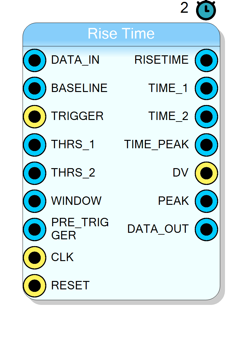
Pin Description
(16 / 32 bit). One sample is processed per clock.
DATA_IN. Use a running average or a
constant pedestal to centre the waveform around zero.
Typical value for 10 % is
0x199A.
0xE666 for 16 bit input size.
$$RISETIME = TIME_2 - TIME_1$$
Units: clock cycles (×1/16 when interpolation is enabled).
DATA_IN crossed THRS_1. Same resolution as
RISETIME.
DATA_IN crossed THRS_2.
RISETIME, TIME_* and
PEAK are stable.
y[n]. Primarily for debugging or
downstream processing.
Properties
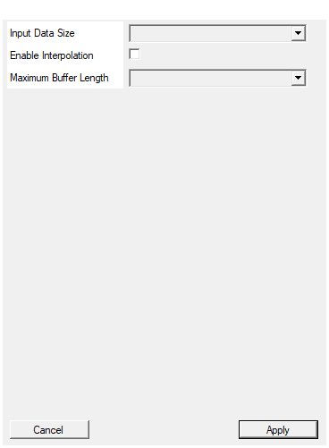
Larger widths increase dynamic range but also resource utilisation (adders, multipliers and memory).
Default: 16
Options: 16 32
Default: False
MAX_RISE_LEN ≥ WINDOW + PRE_TRIGGER.
Default: 1024
Options: 1024 2048
Functional overview
Let $x[n]$ be the input sample stream and $B$ the baseline.
The block first produces the baseline-corrected waveform
$$ y[n] = \max\bigl(0,;x[n] - B\bigr) $$
which is written into a circular buffer of depth MAX_RISE_LEN. A delayed
copy
$$ y_d[n] = y\bigl[n-(WINDOW+PRE_TRIGGER)\bigr] $$
is used for threshold comparison so that the timestamps refer to the original trigger instant.
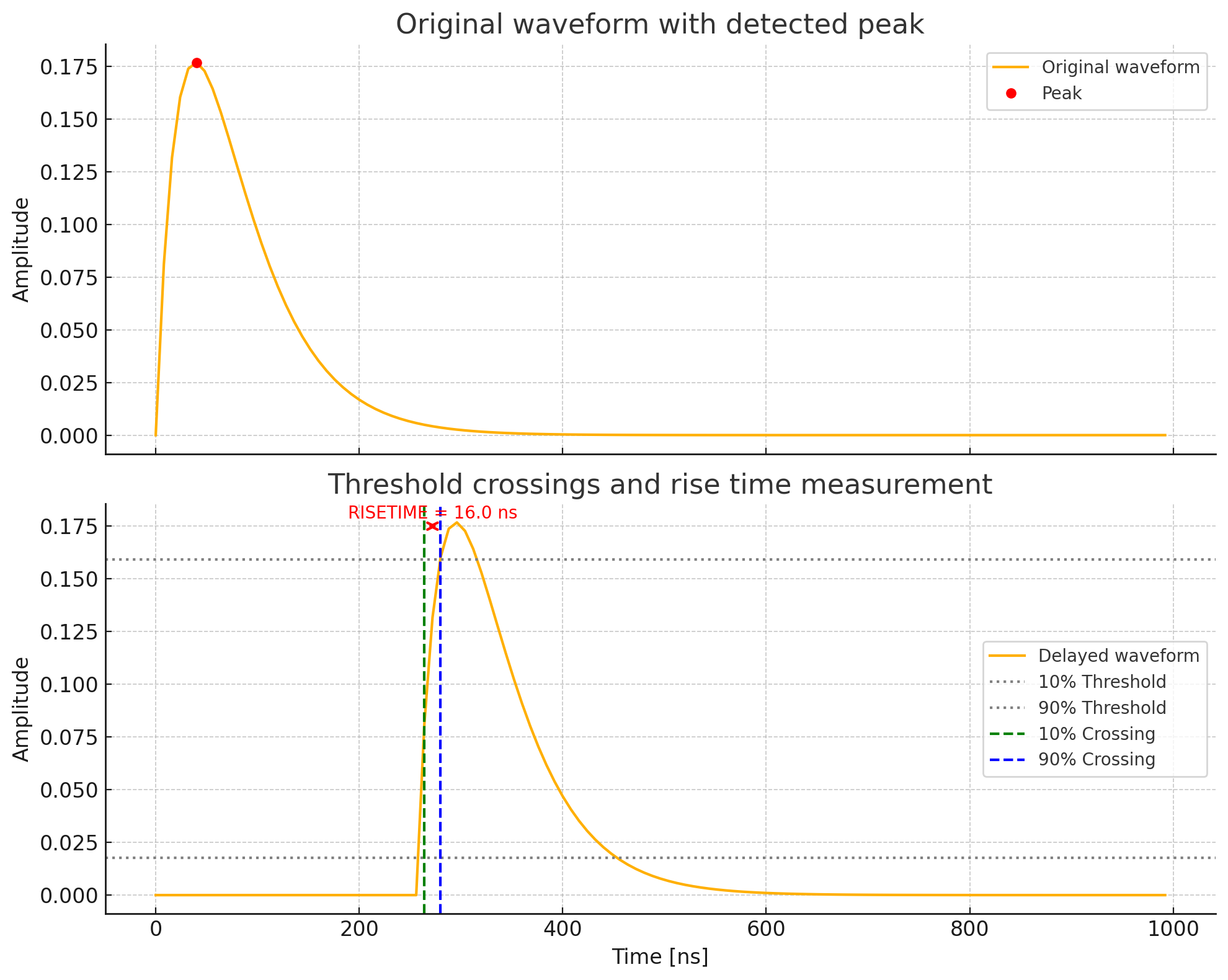
After a trigger, the peak value is searched for WINDOW clock cycles:
$$ PEAK = \max_{0 \le k < WINDOW};y[n_0+k] $$
Absolute thresholds are then generated from the user-defined 16-bit fixed
point coefficients THRS_1 and THRS_2 (0 → 0 %, 65535 → 100 %). The
delayed waveform is scanned further until
$$ y_d[n_1] \ge V_{thr1},\qquad y_d[n_2] \ge V_{thr2},\qquad n_1 < n_2 $$
yielding
$$ TIME_1 = n_1,\quad TIME_2 = n_2,\quad RISETIME = n_2 - n_1 $$
Optional interpolation
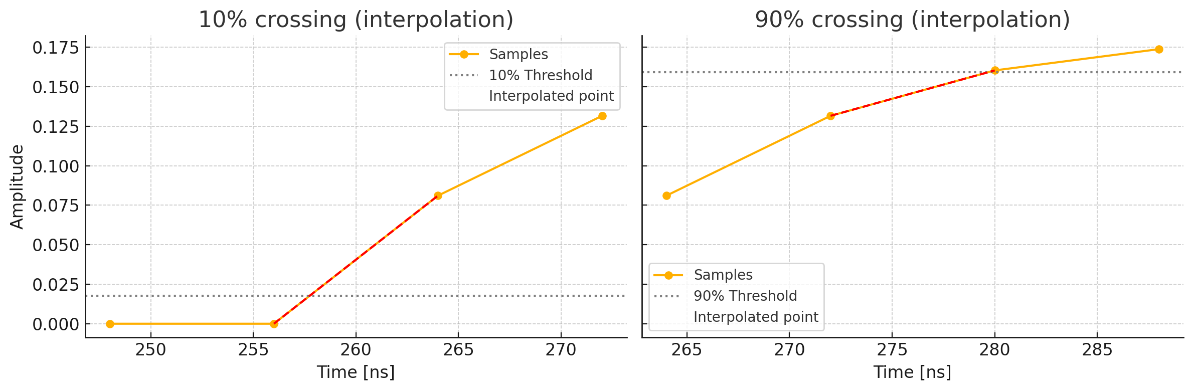
When EN_INTERPOLATION is true, a 4-bit linear interpolation refines the
crossing times giving a resolution of one sixteenth of a sample:
$$ \Delta n = \frac{V_{thr}-y_{prev}}{y_{curr}-y_{prev}};;,\qquad TIME_{INTP}= (n \ll 4) + \left\lfloor 16 ;\Delta n \right\rfloor $$
Timing
Clock to clock latency of the data path DATA_IN → DATA_OUT is 1
cycle (pipeline register).
Latency from the trigger edge to a valid result (DV = '1') is
$$ L \approx PRE_TRIGGER + 2\cdot WINDOW + 6;\text{cycles} $$
The formula covers the peak search, threshold calculation and final scanning
phases. Worst-case latency is obtained when WINDOW equals its maximum
value.
For a 125 MS/s digitizer (4 ns/sample) and settings
THRS_1 = 0.1·2^16, THRS_2 = 0.9·2^16, WINDOW = 128, PRE_TRIGGER = 32:
$$ RISETIME = 7;\text{samples} ; \Rightarrow ; 56;\text{ns} $$
Example – n/γ discrimination with a ³He proportional counter (125 MS/s)
Theory in brief
In a ³He proportional tube, neutron capture (n + ³He → p + ³H + 764 keV) releases two heavy charged particles that deposit energy along a several-cm track. The resulting current pulse has a fast electron component (tens of ns) and a slow ion component (hundreds of ns–µs). After the charge-sensitive preamplifier (≈ RC integration), the output can be modeled as the sum of two exponentials:
[ v(t)=A_f\left(1-e^{-t/\tau_f}\right)+A_s\left(1-e^{-t/\tau_s}\right),\quad \tau_f \ll \tau_s ]
For γ interactions (mainly Compton electrons), (A_s) is small and the pulse is dominated by the fast term → shorter 10–90 % rise time. For neutrons, the slow ion term contributes significantly, stretching the leading edge → longer rise time. Measuring
[ RISETIME = t_{90%}-t_{10%} ]
therefore discriminates n/γ. (If only one exponential is present, (t_{p%}=-\tau \ln(1-p)) and (RISETIME\approx 2.2,\tau); the presence of a second slow component effectively increases the measured rise time.)