
RF AM Modulator
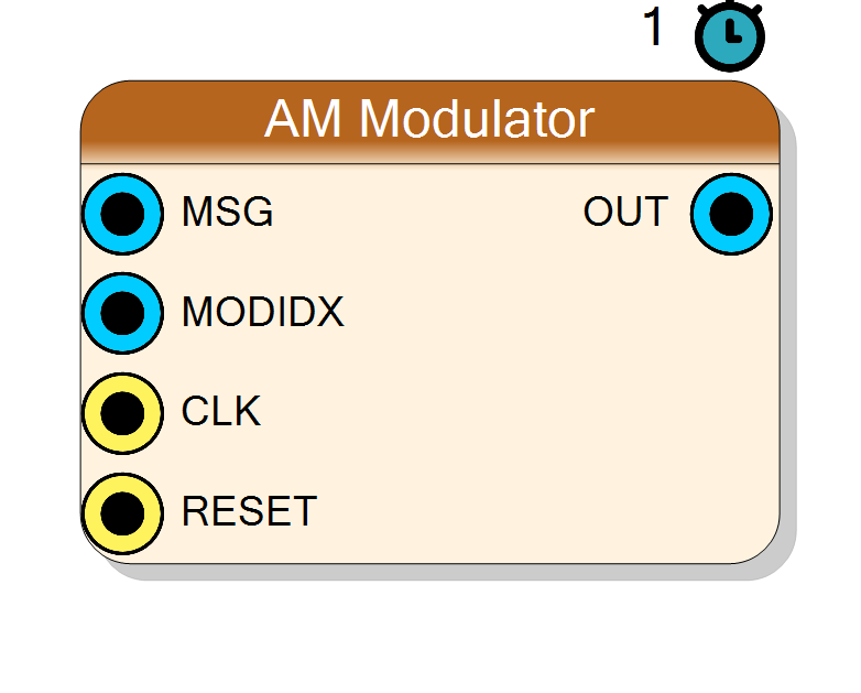
Amplitude modulator: y = (1 + m*msg) * carrier (full AM) or y = m*msg*carrier (DSB-SC, suppressed carrier). Real message in, real modulated signal out. The carrier can be an internal NCO (fixed frequency in Hz), an external carrier waveform, or an internal NCO steered by a run-time tuning word. The modulation index m is a run-time pin, so it can be swept live, including overmodulation m > 1.
Introduction
The AM Modulator multiplies a carrier by a message-derived envelope:
full AM : y[n] = (1 + m*msg[n]) * carrier[n]
DSB-SC : y[n] = m*msg[n] * carrier[n]
msg is a signed real input normalised to its own full scale; m is the
modulation index supplied on the MODIDX run-time pin. The Carrier
Source property selects one of three carrier origins:
- Internal - an on-chip NCO running at Carrier Freq (Hz). The 32-bit
phase tuning word
word = round(f_carrier / Fs * 2^32)is computed at compile time from Carrier Freq and the Fs property and baked into the core (no pin). - External Carrier - the full carrier waveform is taken from the CARRIER input pin (no internal NCO, no cos LUT).
- Runtime Tuning Word - an internal NCO whose phase increment comes from
the 32-bit TUNEWORD run-time pin:
TUNEWORD = round(f / Fs * 2^32), so the carrier frequency can be retuned live from the fabric.
This block uses the standard property grid (no custom designer).
Pin Description
InputSize bits, treated as full-scale
normalised (msg / 2^(InputSize-1)).
Q(MOD_Q=14) signed fixed point:
MODIDX = round(m * 2^14). Always present. Bus width = 14 + ceil(log2(MaxModIndex)) + 1 (see the width table).
InputSize + OUT growth bits (growth is
2..5 depending on Max Modulation Index).
InputSize bits.
round(f_carrier / Fs * 2^32).
Present ONLY when Carrier Source = Runtime Tuning Word. Unsigned.
Properties
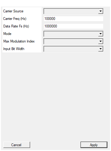
Internal: NCO at Carrier Freq (Hz), tuning word computed from Fs at compile. External Carrier: full carrier waveform on the CARRIER pin. Runtime Tuning Word: NCO tuned by the runtime TUNEWORD pin.
Carrier origin. Internal: NCO at Carrier Freq (Hz), tuning word baked at compile time. External Carrier: full carrier waveform on the CARRIER pin. Runtime Tuning Word: NCO tuned by the 32-bit TUNEWORD pin. Default Internal. Changing this redesigns the core (pin set changes).Default: Internal
Options: Internal External Carrier Runtime Tuning Word
Internal NCO carrier frequency (Hz). Used only for ‘Internal’; the tuning word = round(f / Fs * 2^32) is computed at compile time.
Internal NCO carrier frequency in Hz. Used ONLY in Internal mode; the constant tuning wordround(f / Fs * 2^32) is computed at compile time.
Default 100000.
Default: 100000
Sample rate (Hz), for the internal carrier frequency.
Sample rate in Hz. Used only to convert Carrier Freq (Hz) to the internal tuning word. Default 1000000.Default: 1000000
AM: with carrier. DSB-SC: suppressed carrier (mmsgcarrier).
AM: transmitted carrier,y = (1 + m*msg)*carrier. DSB-SC:
suppressed carrier, y = m*msg*carrier. Default AM.
Default: AM
Options: AM DSB-SC
Upper bound on the runtime MODIDX pin (m). Sets the MODIDX bus width (MOD_Q + log2(max) + 1) and the output headroom. Use >1 for overmodulation.
Upper bound on the run-time MODIDX index m. Sets the MODIDX bus width
(MOD_Q + ceil(log2(max)) + 1) and the output headroom. Use a value
1 to allow overmodulation without clipping. One of 1, 2, 4, 8, 16, default 2. Changing it redesigns the core (datapath widths change).
Default: 2
Options: 1 2 4 8 16
Message (and external carrier) bit width.
Message (and external carrier) bit width. Range 4 to 32, default 16.Default: 16
Options: 4 5 6 7 8 9 10 11 12 13 14 15 16 17 18 19 20 21 22 23 24 25 26 27 28 29 30 31 32
Usage
Runtime pins vs static properties
Read this carefully - the split determines what you must drive from the fabric versus what is fixed at synthesis.
- MODIDX is ALWAYS a run-time pin (there is no modulation-index
property). Its value is the fixed-point index
MODIDX = round(m * 2^MOD_Q)with MOD_Q = 14. Example:m = 0.7->round(0.7 * 16384) = 11469. - TUNEWORD is a run-time pin, present ONLY for Carrier Source = Runtime
Tuning Word:
TUNEWORD[31:0] = round(f_carrier / Fs * 2^32). - CARRIER is a signal pin, present ONLY for Carrier Source = External Carrier.
- Carrier Source, Carrier Freq, Fs, Mode, Max Modulation Index and Input Bit Width are static properties resolved at compile time. Carrier Freq is used only in Internal mode (to bake the constant tuning word); Fs is used only to convert Hz to a tuning word.
Modulation-index Q-format and MODIDX bus width
The MODIDX pin is Q(MOD_Q) signed fixed point. Its width is set by the
Max Modulation Index property (an upper bound on m, one of
1, 2, 4, 8, 16):
MOD_INT_BITS = ceil(log2(MaxModIndex)) (integer bits of m)
MODIDX width = MOD_Q + MOD_INT_BITS + 1 (Q14 fraction + int + sign)
| Max Modulation Index | MOD_INT_BITS | MODIDX width | OUT growth (bits) |
|---|---|---|---|
| 1 | 0 | 15 | 2 |
| 2 | 1 | 16 | 2 |
| 4 | 2 | 17 | 3 |
| 8 | 3 | 18 | 4 |
| 16 | 4 | 19 | 5 |
Choosing a larger Max Modulation Index widens the MODIDX bus and adds output
headroom so that (1 + m)*carrier does not clip - this is what enables
intentional overmodulation (m > 1).
Datapath
mterm = (MODIDX * msg) >> (InputSize - 1) (Q(MOD_Q), m*msg)
env = (1 << MOD_Q) + mterm (full AM)
env = mterm (DSB-SC)
y = (env * carrier) >> MOD_Q
The internal NCO carrier amplitude is InputSize-bit (a 4096-entry cosine
LUT, LUT_BITS = 12, phase accumulator 32-bit).
Bit widths
MSG,CARRIER: signedInputSizebits.TUNEWORD: unsigned 32 bits.MODIDX: signed, see table above.OUT: signedInputSize + OUT growthbits (growth from the table).
Latency and throughput
#pragma HLS PIPELINE II=1: one output sample per clock.- All ports use the
ap_noneinterface (no ready/valid handshake). - INTERFACE pragmas are emitted before any statement so Vitis keeps
ap_ctrl_none(the block is free-running; SciCompiler never drivesap_start).
Reset
RESET is the HLS synchronous reset (ap_rst). It clears the internal NCO
phase accumulator (Internal / Runtime Tuning Word modes).
Typical applications
- AM broadcast-style modulation of a baseband message onto a carrier.
- DSB-SC for coherent / product-detector links.
- Live index sweeps and overmodulation tests by driving MODIDX (and, in Runtime Tuning Word mode, TUNEWORD) from registers.
Resources & Timing
-
Latency: 1 clock cycle (II=1)
-
Throughput: 1 sample per clock (II=1)
Implemented with Vitis HLS. Internal / Runtime-Tuning-Word modes use a 4096-entry (LUT_BITS=12) cosine ROM plus a 32-bit phase accumulator; External Carrier mode drops the LUT entirely. One or two multipliers (mmsg and envcarrier). Static params (mode, DSB, constant tuning word, Max Modulation Index, InputSize) drive the HLS unique name; MODIDX and TUNEWORD are runtime pins and are excluded from it.