
TRP NEW
Second generation of the TRP MCA trapezoidal shaper for transistor-reset pre-amplifiers. It keeps the fully-pipelined Jordanov dual-filter architecture of TRP MCA and adds: a wider CFD validation window that removes the trigger losses observed at high rate with slow detectors, a programmable baseline pre-guard, leakage correction applied to the energy path, a complete on-chip statistics block (ICR/OCR, reset and pileup counters) and an optional in-IP pileup rejector that decides at the energy sampling point (no added latency) with debug flags.
Introduction
The TRP NEW block implements the same dual trapezoidal-filter chain as TRP MCA (fast trigger filter + slow energy filter for transistor-reset pre-amplifiers) and supersedes it. The improvements come from a systematic investigation on real 2 Mcps SDD data:
- Trigger validation window widened to (TRIG_K + TRIG_M)·2 samples (the legacy TRIG_K·2 window expired before the zero crossing when the detector rise time exceeded a few samples: up to ~45 % of the pulses produced no trigger at all, and their un-vetoed trapezoids corrupted the baseline average, producing rate-dependent ghost peaks that grew with the baseline length).
- Leakage correction on the energy path: the
LEAKAGE_M/LEAKAGE_Qramp is now subtracted from the signal that feeds the energy trapezoid (in TRP MCA it only drove theLEAKAGE SIGmonitor output). - Baseline pre-guard (
BL PRE GUARDpin): the baseline average can be stopped a programmable number of samples before each trigger, so the rising edge of the pulse never enters the average. - Statistics block: input/output/reset/lost/pileup counters and
windowed ICR/OCR rate meters, with a synchronous
RESET STATclear. - Optional pileup rejector (compile-time property): discards both events of a too-close pair or only the second event riding on the tail of the first. Decisions are taken at the energy sampling point, so no output is delayed and the block latency does not change.
With ENABLE_PILEUP_REJECTOR = False and the new input pins left
unconnected the block behaves exactly like TRP MCA except for the
wider (correct) trigger validation window.
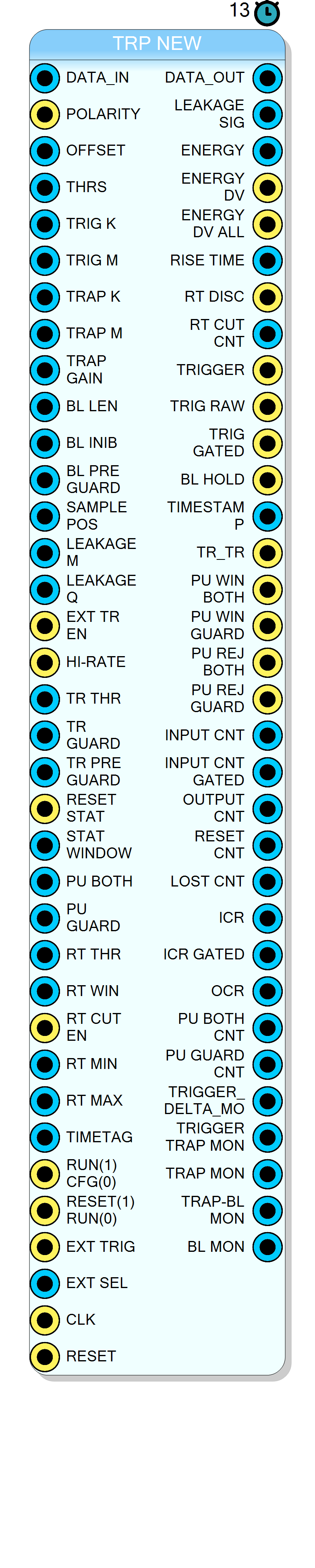
Pin Description
1 = pulses are positive; 0 = pulses are negative. Selects internal inversion path.
TRAP_M − TRAP_K samples. Minimum 2 (a lower value is used as 2).
0 disables the baseline restorer.
≥ 2·TRAP_K + TRAP_M + BL_PRE_GUARD.
0 = legacy behaviour. Upper bound set
by the BL_PRE_GUARD_MAX property. Remember to enlarge BL_INIB
accordingly.
Minimum 4: a lower value is used as 4.
≈ TRAP_K + (TRAP_M − TRAP_K)/2. Minimum 1 (a lower value is used as 1).
LEAKAGE SIG monitor. 0 = off.
1 = use pin TR_RESET; 0 = use automatic reset detector.
0 when unconnected). With it high
the post-reset trigger inhibition preroll is zero, so triggering
resumes as soon as the reset guard expires: fewer events lost at high
rate, at the cost of accepting triggers while the baseline is still
recovering.
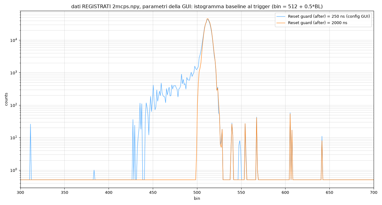
≥ TRAP_K + TRAP_M + TR_RESET_PRE_GUARD + margin — a shorter guard lets the negative recovery pollute the baseline (left tail in the baseline histogram, see the Reset veto and guard sizing section).
0 disables the rate meters.
0 = rule off. Clamped to SAMPLE_POS at runtime (see How the two rules are evaluated).
PILEUP_DIST_BOTH and this value only the SECOND event is discarded. 0 = rule off. Unbounded: it is evaluated on arrival of the second trigger.
0 disables the measure. Typical: just above 4× the per-sample noise.
[trigger−7, trigger−7+RT_WINDOW]. Cover the pulse rise plus the unresolved-pileup region; default 16. Max 255 (ring is 256 deep). Keep RT_WINDOW − 7 ≤ SAMPLE_POS: the rise time is latched RT_WINDOW − 7 samples after the trigger and paired with the event at its sampling point, so a longer window pairs each event with the PREVIOUS event’s rise time (and the first event after a configuration restart carries an undefined one). Minimum 8: a lower value is used as 8.
1 = enable the in-IP rise-time cut (gates only ENERGY DV). 0 (default when unconnected) = no cut, RISE_TIME is informative only.
RT_MIN ≤ rise_time ≤ RT_MAX).
1 = run mode; 0 = configuration/idle. All state (including statistics) is cleared while 0.
1 the internal alignment
delay TRIG_K + TRIG_M is bypassed, retune SAMPLE_POS.
ENERGY DV=1.
ENERGY DV. The energy/timestamp/rise-time registers update on every event.
RESET STAT / RUN_CFG=0). Disjoint from the pileup counters.
PILEUP_DIST_BOTH).
[PILEUP_DIST_BOTH, PILEUP_DIST_GUARD)).
INPUT_CNT increments latched every STAT_WINDOW clocks.
INPUT_CNT_GATED increments latched every STAT_WINDOW clocks.
OUTPUT_CNT increments latched every STAT_WINDOW clocks.
Properties
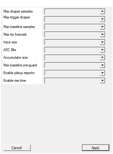
This parameters configure the maximum number of samples used by the trapezoidal. It impact of the RAM memory usage in the FPGA
Maximum depth of the energy delay lines (samples). Larger values allow longer peaking times but consume more block-RAM.Default: 2048
Options: 128 256 512 1024 2048 4096 8192 16384
This parameters configure the maximum number of samples used by the trigger trapezoidal. It impact of the RAM memory usage in the FPGA
Maximum depth of the trigger delay lines (samples). Must be ≥TRIG_K + TRIG_M.
Default: 128
Options: 16 32 64 128 256 512
Maximum number of samples of the baseline moving average (RAM usage). Keep it ABOVE PRE_LEN so the baseline preroll outlasts the shaper start-up transient.
Maximum length of the baseline restorer buffer (samples). Must be ≥ 2^BL_LEN. Keep it ABOVE PRE_LEN so the baseline warm-up outlasts the shaper start-up transient.
Default: 2048
Options: 128 256 512 1024 2048 4096 8192 16384
Number of samples the input can be delayed to let the reset veto anticipate the reset transient (TR PRE GUARD pin upper bound)
Depth of the auxiliary delay line used to hide the reset transient from the trigger path (upper bound ofTR_RESET_PRE_GUARD).
Default: 128
Options: 32 64 128 256 512 1024 2048
Number of bits of the input signal
Width of input busDATA_IN and internal arithmetic datapath. Changing this parameter resynthesises the core.
Default: 24
Options: 12 14 16 20 24 28 32 64
Number of real bits if the ADC connected to the input. (used for saturation and polarity inversion)
Effective ADC resolution used for saturation monitoring and polarity inversion. May differ fromADC_BITS_N.
Default: 20
Options: 12 14 16 18 20 22 24 26 28 30 32
Accumulator size, depends by the adc number of bit and trapezoidal lenght. Short trapezoidal may have 32 bit acc. At least 64 is reccomanded
Accumulator width in the energy filter. Must be chosen to avoid overflow for the longest peaking time and maximum input signal; at least 64 is recommended.Default: 64
Options: 32 48 64 80 96 128
Upper bound (ring size) of the runtime BL_PRE_GUARD pin: the baseline average can be stopped up to this many samples BEFORE the trigger
Ring size (upper bound) of the runtimeBL_PRE_GUARD pin.
Default: 64
Options: 16 32 64 128 256
Compile the in-IP pileup rejector. Decisions are taken at the energy sampling point, so no output is delayed and the latency is the legacy one. PILEUP DIST BOTH is clamped to SAMPLE_POS at runtime (a second pulse arriving after the first one was sampled cannot corrupt it; use PILEUP DIST GUARD ~ TRAP_K + TRAP_M - SAMPLE_POS for the tail). Default False = rejector logic compiled out.
Compile the in-IP pileup rejector. Decisions are taken at the energy sampling point, so no output is delayed and the latency is the legacy one. Default False = rejector logic compiled out (same behaviour as TRP MCA except the corrected trigger window).Default: False
Options: False True
Compile the rise-time measure and its optional cut. When True the RT_THR/RT_WIN/RT_CUT_EN/RT_MIN/RT_MAX inputs and the RISE_TIME/RT_DISCARDED/RT_CUT_CNT outputs appear. The measure is inert until RT_THR is set; the cut acts only on ENERGY DV (never on ENERGY DV ALL).
Compile the rise-time measure and its optional cut. When True the RT_THR / RT_WIN / RT_CUT_EN / RT_MIN / RT_MAX inputs and the RISE_TIME / RT_DISCARDED / RT_CUT_CNT outputs appear on the symbol. The measure is inert until RT_THR is set; the cut acts only onENERGY DV (never on ENERGY DV ALL).
Default: True
Options: False True
Theory of operation
A Jordanov trapezoid is obtained by the difference of two rectangular moving sums:
$$ T[n] = \sum_{i=0}^{k-1}x[n-i] - \sum_{i=k+m}^{2k+m-1}x[n-i] $$
where k is the peaking length and m the gap between the two sums
(flat-top duration = m − k). See the TRP MCA guide for the full
derivation; this page documents the differences and the new sections.
Trigger filter
Parameters TRIG_K, TRIG_M, THRS. When the delta signal crosses
THRS a trigger candidate is armed and validated on the subsequent zero
crossing (bipolar CFD detection). The validation window is
(TRIG_K + TRIG_M)·2 samples: it always covers the zero crossing,
which arrives roughly TRIG_M + rise-time samples after arming. Choose
TRIG_K comparable to the input rise time (in samples) for the best
time resolution.
The impact of the corrected window, measured on real 2 Mcps SDD data with a ~45 ns rise time: the legacy window lost up to 45 % of the pulses and their un-vetoed trapezoids polluted the baseline. Same data, same parameters, legacy vs TRP NEW:
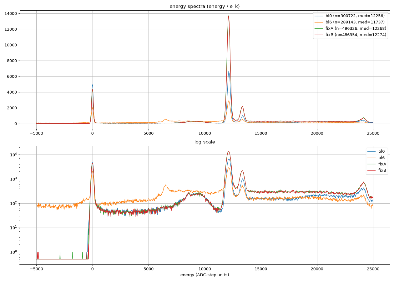
The Kα peak more than quadruples in counts, the negative shoulder and the ghost replicas disappear, and the throughput gains ~70 %.
Energy filter and leakage correction
As in TRP MCA (TRAP_K, TRAP_M, TRAP_GAIN, accumulator width
LARGE_ACC_BITS), but the input sample is first corrected as
$$ x_\ell[n] = x[n] - \frac{L[n]}{2^{20}},\qquad L[n] = \begin{cases} L[n-1] + \text{LEAKAGE_M} & \text{while no reset}\ \text{LEAKAGE_Q} & \text{immediately after a reset} \end{cases} $$
and $x_\ell[n]$ feeds both the LEAKAGE SIG monitor and the energy
trapezoid. With LEAKAGE_M = LEAKAGE_Q = 0 the correction is inert.
LEAKAGE_M is expressed in ADC counts per sample times $2^{20}$.
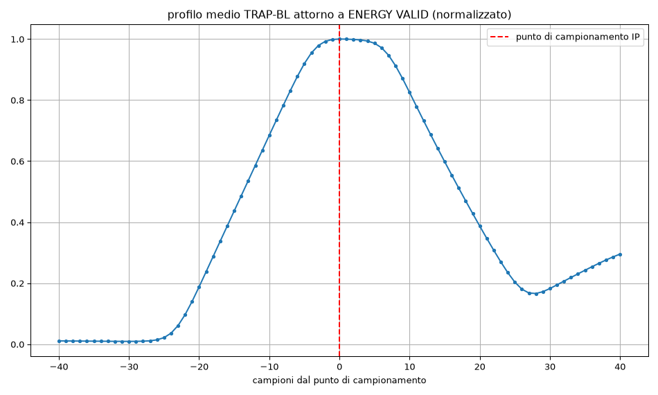
The energy is sampled SAMPLE_POS samples after the trigger: centre it
on the flat top, SAMPLE_POS ≈ TRAP_K + (TRAP_M − TRAP_K)/2. The
aligned average of TRAP-BL around the sampling strobe, measured on
real data, shows the sampling point sitting exactly on the flat-top
maximum with the recommended setting:
Baseline restorer with pre-guard
A moving average of depth $2^{\text{BL LEN}}$ updated only outside the
hold windows (each validated trigger re-arms BL_INIB samples of hold;
the reset veto holds as well). The BL PRE GUARD pin feeds the
average through a delay line while the hold is applied un-delayed: the
net effect is that the average stops BL PRE GUARD samples before
each trigger, keeping the pulse leading edge out of the baseline.
Set BL_INIB ≥ 2·TRAP_K + TRAP_M + BL_PRE_GUARD + margin so the whole
trapezoid (now shifted by the pre-guard) stays inside the hold.
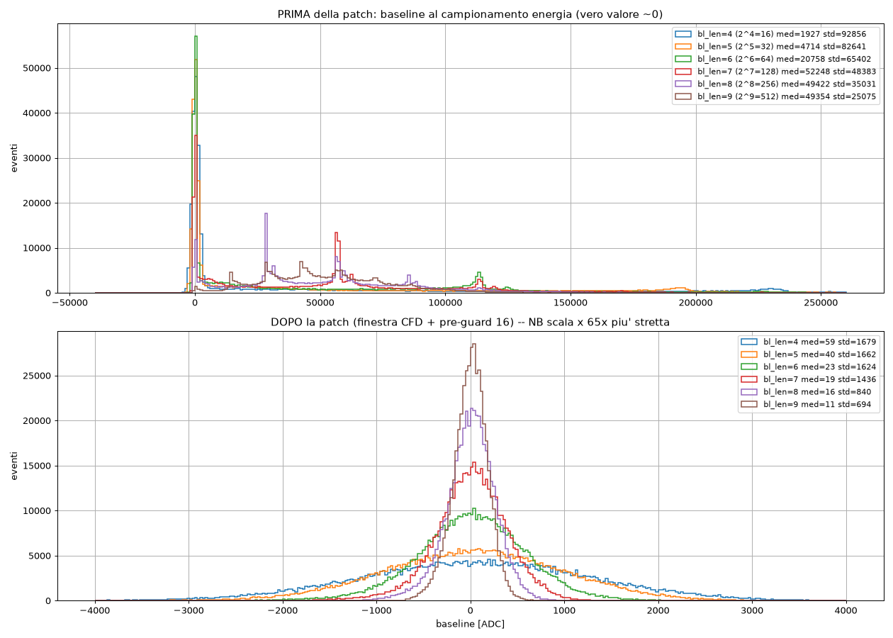
The baseline value sampled at each event is the direct spectral error: below, its distribution measured on real 2 Mcps data for baseline lengths 2^4…2^9, legacy (top) versus TRP NEW (bottom — note the ~65× tighter x-scale). The legacy multimodal spikes are the quantized ghosts of un-triggered trapezoids; TRP NEW is Gaussian around zero at every length:
Reset veto and guard sizing
After each pre-amplifier reset the energy trapezoid dives strongly
negative and needs TRAP_K + TRAP_M samples to recover once the step
has transited. The reset veto must keep the baseline held for that
whole time, therefore:
$$ \text{TR_RESET_GUARD (after)} ;\ge; \text{TRAP_K} + \text{TRAP_M}
- \text{TR_RESET_PRE_GUARD} + \text{margin (~100 ns)} $$
A too-short guard produces a negative tail on the left side of the baseline distribution (and a low-energy tail on the peaks), because triggers arriving a few hundred samples after a reset sample a baseline still polluted by the negative recovery. Measured on real data with a 625+125 ns shaping: guard 250 ns (blue) vs 2000 ns (orange):
Statistics block
All counters are 32 bit, cleared by RUN_CFG = 0 or by a high level on
RESET STAT:
| output | meaning |
|---|---|
INPUT CNT |
raw CFD triggers, before the reset veto |
INPUT CNT GATED |
CFD triggers outside the reset veto |
OUTPUT CNT |
energy words emitted (post pileup rejection) |
RESET CNT |
pre-amplifier resets (one count per reset) |
LOST CNT |
triggers suppressed by the reset veto |
PU BOTH CNT |
events discarded by the pileup both rule (2 per pair) |
PU GUARD CNT |
events discarded as second in guard |
ICR / ICR GATED / OCR |
the corresponding counts latched every STAT WINDOW clock cycles |
Set STAT WINDOW equal to the clock frequency to read ICR/OCR directly
in counts per second (0 disables the rate meters). Note that
INPUT CNT counts the internal CFD even when an external trigger is
selected through EXT SEL.
Pileup rejector (optional)
Enabled at synthesis time by the ENABLE_PILEUP_REJECTOR property.
Let dt be the distance between consecutive accepted triggers (the
comparison chain is pairwise recursive: each trigger is compared with
the previous one even if that one was already discarded):
dt < PU BOTH→ both events are discarded;PU BOTH ≤ dt < PU GUARD→ only the second event is discarded (it rides on the tail of the first);- a threshold set to
0disables that rule.
How the two rules are evaluated. The second rule (guard) is
decided on arrival of the second trigger by comparing the distance from
the previous one, whatever the shaping length: PU GUARD is unbounded
and costs nothing. The both rule is retroactive for the first event:
its verdict is applied when that event is sampled, SAMPLE_POS samples
after its trigger, exactly where the legacy strobe fires. It is complete
only if PU BOTH ≤ SAMPLE_POS, which is also the physics: a second
pulse arriving after the first one has been sampled cannot corrupt that
sample (baseline held, trapezoid already read) — discarding the second
one is the guard rule’s job. PU BOTH is therefore clamped to
SAMPLE_POS at runtime. Recommended: PU BOTH = SAMPLE_POS,
PU GUARD ≈ TRAP_K + TRAP_M − SAMPLE_POS (tail of the first trapezoid
beyond the sampling point) or more to protect the baseline.
Minimum values. Some delay-line taps have a minimum, enforced inside
the IP (a lower pin value is used as the minimum): TRIG_K, TRIG_M
≥ 3, TRAP_K, TRAP_M, TR_RESET_PRE_GUARD ≥ 2, SAMPLE_POS ≥ 1,
BASELINE_LEN ≥ 2 when not 0, BL_PRE_GUARD ≥ 4, RT_WINDOW ≥ 8.
These are the hard limits measured in RTL simulation (shorter taps would
read a stale delay-line slot in hardware); short pre-guard values are
served from registers, so BL_PRE_GUARD = 4 is exact.
Two pulses closer than the CFD resolution produce a single trigger and
cannot be separated by dt: the residual sum peak must be handled by
energy cuts.
Alignment. Nothing is delayed: monitors, triggers and windows are on
the legacy time base; ENERGY DV, ENERGY, TIMESTAMP, RISE TIME
and the reject markers (PU REJ BOTH, PU REJ GUARD) fire at the
flat-top sampling point of the trapezoid (SAMPLE_POS after the
trigger) like the legacy strobe — rejected events show their marker
exactly where their energy would have been sampled, which makes
threshold tuning on the scope immediate. PU WIN BOTH / PU WIN GUARD
are the live windows opened by the last trigger.
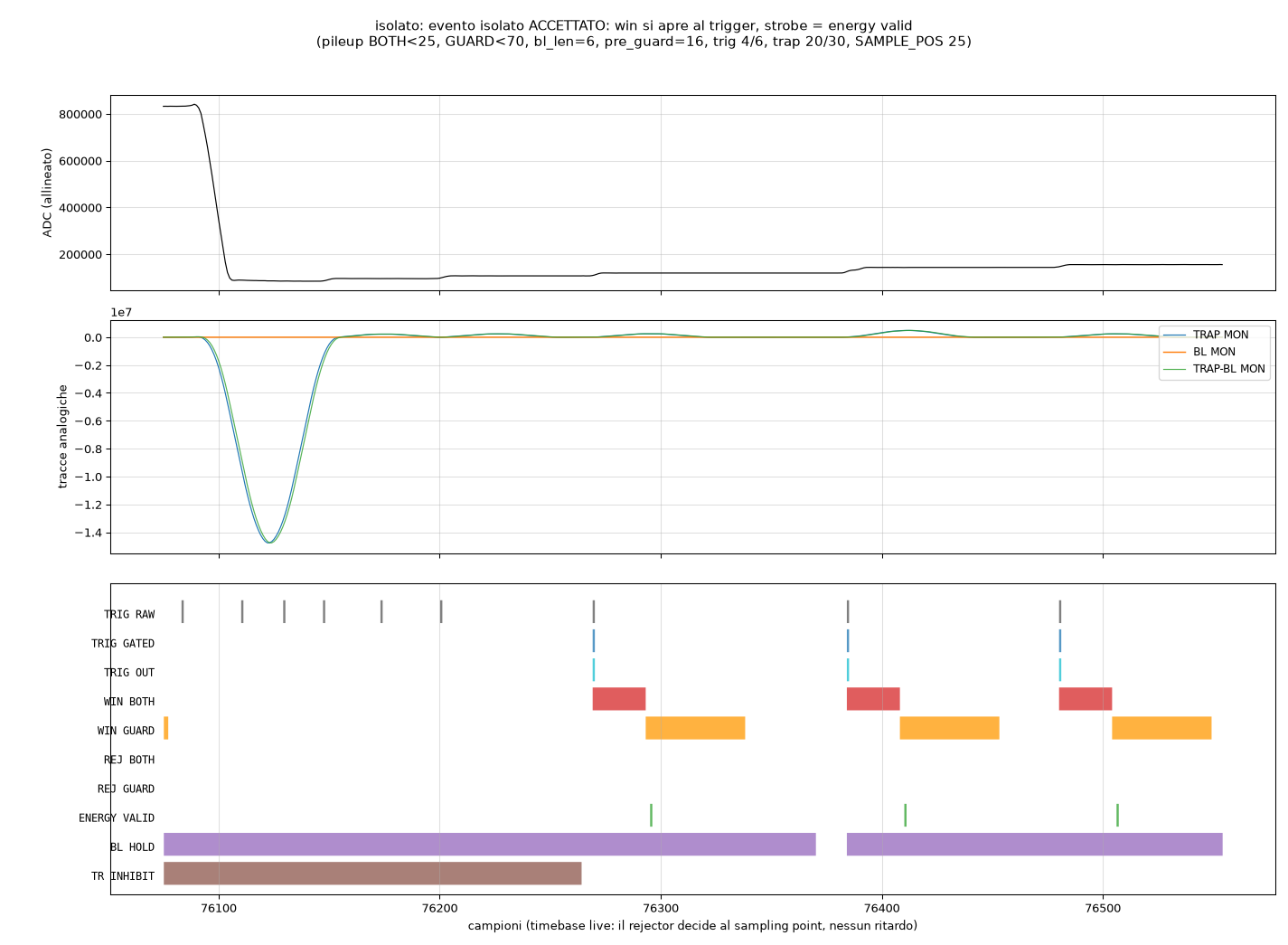
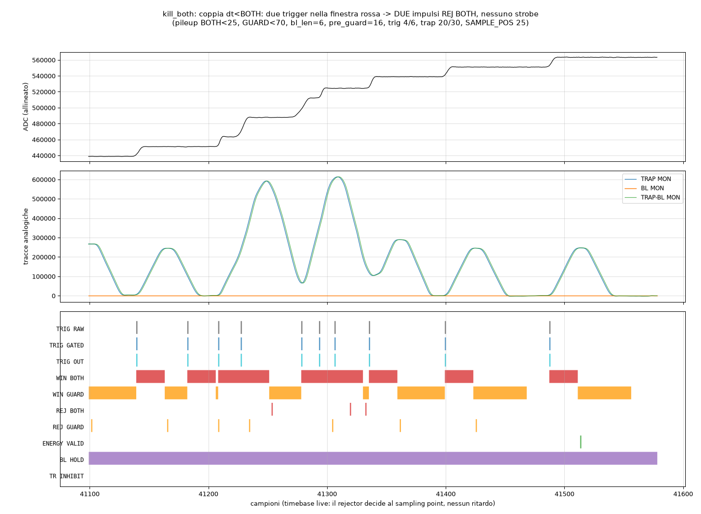
Timing diagrams — real 2 Mcps SDD waveforms as the acquisition
software shows them (trap 20/30 samples, SAMPLE_POS 25,
PU BOTH 25, PU GUARD 70). An isolated accepted event: the windows
open at the trigger, ENERGY DV fires on the flat top:
A pair closer than PU BOTH: both triggers fall inside the red window,
two PU REJ BOTH markers, no strobe:
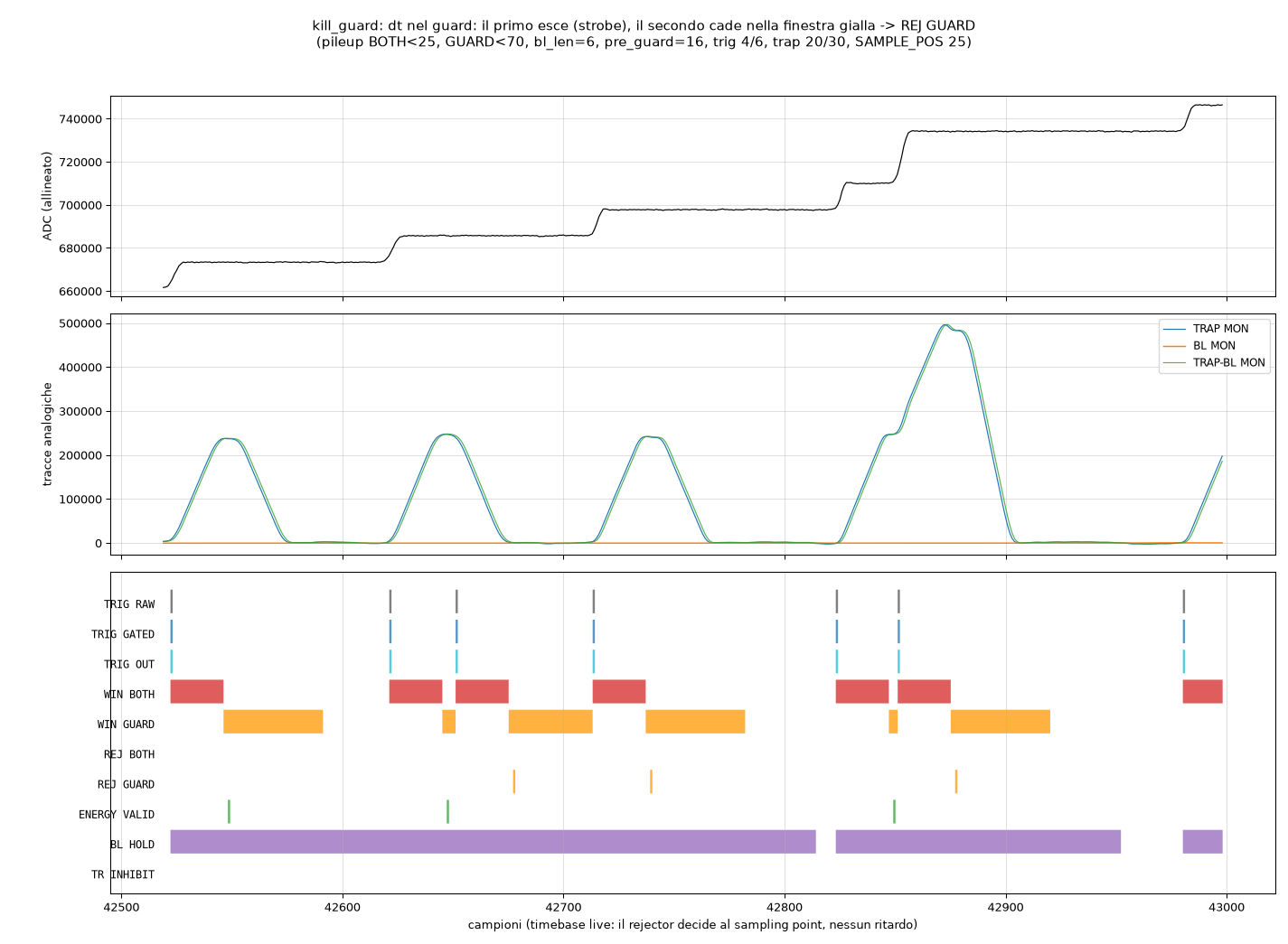
Events in the guard zone: the first is sampled (ENERGY DV), the
followers fall in the yellow window and emit PU REJ GUARD:
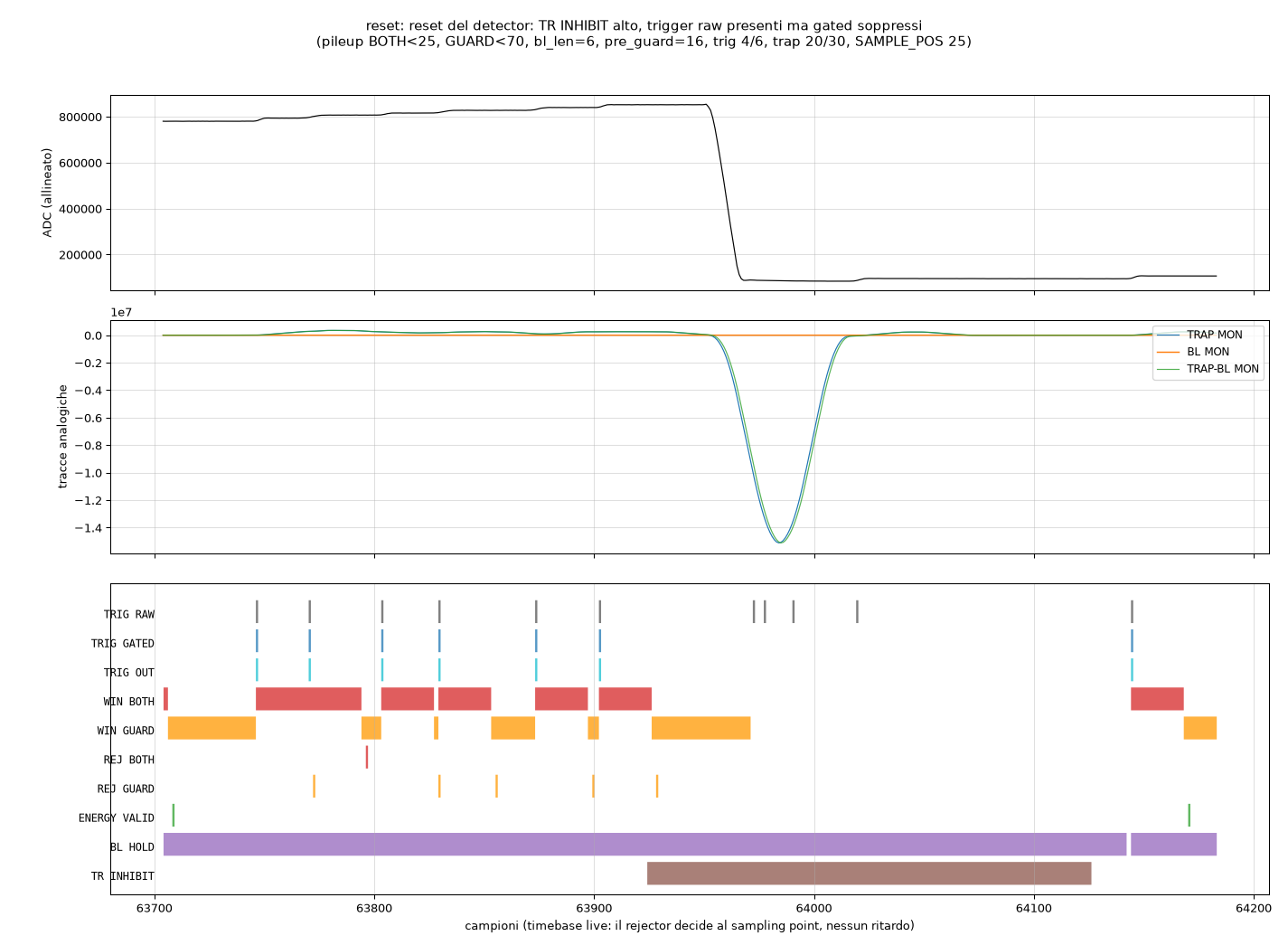
A pre-amplifier reset: TR INHIBIT rises before the visible ADC cliff
(the TR_RESET_PRE_GUARD look-ahead), raw triggers inside the veto have
no gated counterpart and no energy is emitted:
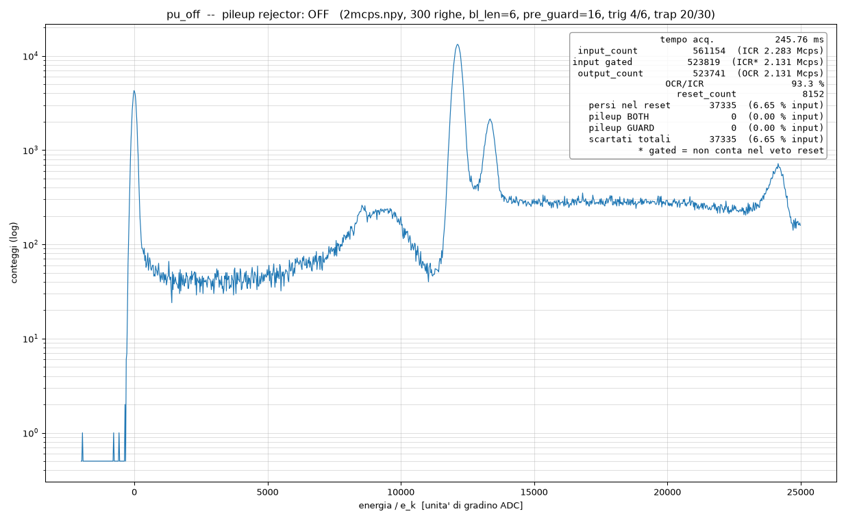
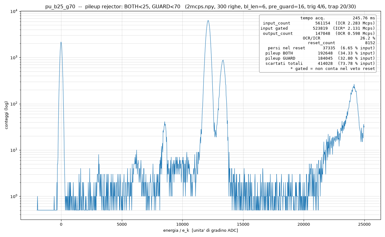
Measured effect on the spectrum (real 2 Mcps data, 245 ms, statistics
overlay from the IP counters). Rejector off, then PU BOTH = SAMPLE_POS
and PU GUARD = 70: the inter-peak continuum drops by about two orders
of magnitude and the partial-pileup bump disappears; the residual sum
peak (unresolved coincidences) is the target of the rise-time cut below:
Rise-time measure
In parallel with every energy word the block emits RISE TIME: the
number of samples, within a sliding window of RT WIN samples ending
just after the trigger ([trigger − 7, trigger − 7 + RT WIN]), where the
4-sample derivative of the (aligned, leakage-corrected) input exceeds
RT THR. A clean step gives ≈ input rise time + 4; every
additional step landing inside the window adds its own contribution
regardless of the separation. Unresolved pileup (two pulses closer than
the CFD resolution, which produce a single trigger and a summed energy)
therefore shows a distinctly larger value: on real 2 Mcps SDD data a
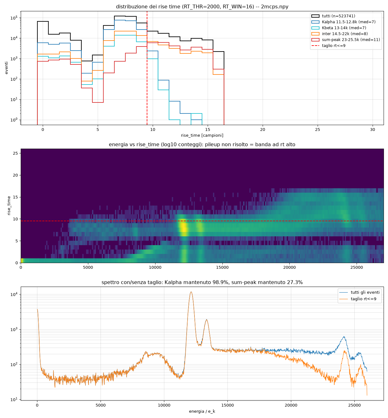
downstream cut at RISE TIME ≤ 9 kept 98.9 % of the Kα peak while
removing 73 % of the sum peak. RT THR = 0 disables the measure
(output 0). The value is meaningless for events started by the external
GIN trigger. The whole feature (ports included) is compiled in by the
ENABLE_RISETIME property.
Measured on real 2 Mcps data (RT THR 2000 ADC, RT WIN 16): the
rise-time distributions per energy region, the energy-vs-rise-time map
(the unresolved-pileup band sits clearly above the photopeaks) and the
spectrum with/without the cut:
Optional in-IP cut: with RT CUT EN high an event is accepted only
if RT MIN ≤ RISE TIME ≤ RT MAX. The cut gates only the filtered
ENERGY DV: ENERGY DV ALL and the ENERGY/TIMESTAMP/RISE TIME
registers are untouched, so downstream logic can always see every event
with its rise time and re-apply its own selection. Each cut event emits
a RT DISCARDED pulse (aligned like the strobes) and increments
RT CUT CNT. With the pileup rejector enabled the cut is applied AFTER
the pileup rules, so RT CUT CNT and the pileup counters are disjoint:
ENERGY DV ALL = ENERGY DV + RT CUT + pileup both + pileup guard.
Unfiltered energy valid
ENERGY DV ALL pulses for EVERY sampled event — accepted and
pileup-rejected — with the same alignment as ENERGY DV in both modes.
The ENERGY / TIMESTAMP / RISE TIME output registers update on
every event as well: the pileup rejector only suppresses the filtered
ENERGY DV. Downstream logic can thus either take the filtered stream
(ENERGY DV) or the full stream (ENERGY DV ALL) and apply its own
rejection using RISE TIME and the pileup counters.
Timing
- Same latencies as TRP MCA with or without the rejector.
FPGA resources
As TRP MCA, plus one small delay line of depth BL_PRE_GUARD_MAX, the
rise-time rings (2 × 256 bit) and, when the pileup rejector is compiled
in, two rings of depth PRE_LEN (2 bit + 1 bit) parallel to the sampler
delay line: about 3 BRAM18 in total at PRE_LEN = 4096.
Typical use-case
A transistor-reset SDD or HPGe detector at high rate (≥ 500 kcps). At
2 Mcps, enabling the rejector with PU BOTH = SAMPLE_POS and
PU GUARD ≈ 2·TRAP_K + TRAP_M cleans the inter-peak continuum by about
two orders of magnitude at the cost of the corresponding throughput;
the statistics outputs give the live ICR/OCR balance needed to compute
dead-time-corrected activities.