
Energy Sampler
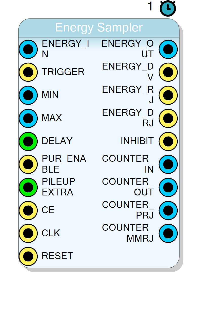
Energy sampling block with pile-up rejection (PUR), programmable energy window filtering, and event counting. Samples the energy value at a programmable delay after the trigger, with optional rejection of pile-up events.
Introduction
The Energy Sampler block captures the energy value from a shaped pulse at a programmable time after the trigger event. This is essential for accurate pulse-height analysis in Multi-Channel Analyzer (MCA) applications.
The block implements pile-up rejection (PUR) to detect and discard events where two or more pulses arrive too close together, which would result in incorrect energy measurements.
Additionally, the block provides energy window filtering to accept only events within a programmable MIN/MAX range, and maintains counters for monitoring trigger rates and rejection statistics.
Pin Description
DELAY clock cycles after this trigger.
ENERGY < MIN are rejected and counted in COUNTER_MMRJ.
ENERGY > MAX are rejected and counted in COUNTER_MMRJ.
Enable pile-up rejection logic.
1– Enable PUR: reject events with pile-up0– Disable PUR: accept all triggered events
Properties
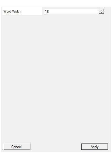
Width of the input data in bits
Bit-width of the energy input and output signals. Applies toENERGY_IN, ENERGY_OUT, MIN and MAX signals.
Acceptable range: 4 … 32, default 16.
Default: 16
Range: 4 – 32
Usage
Functional Overview
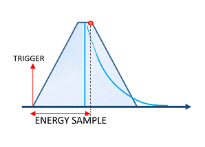
The figure shows:
- TRIGGER: The trigger pulse marking the beginning of the event
- ENERGY SAMPLE: The sampling point where the energy value is captured (after the programmable delay)
The energy value is sampled at a fixed delay after the trigger, corresponding to the peak of the shaped pulse where the energy information is most accurate.
State Machine Operation
The Energy Sampler implements a 4-state machine for pile-up detection and energy sampling:
State 0 (Idle): Waiting for trigger
- When trigger arrives, start delay countdown and move to State 1
- If PUR is enabled, set INHIBIT output
State 1 (Delay): Counting down to sampling point
- If another trigger arrives during delay (pile-up detected):
- Restart delay counter
- Set ENERGY_DRJ (double rejection)
- Move to State 2 (reject mode)
- If delay completes without pile-up:
- Sample energy and check MIN/MAX window
- If within window: output ENERGY_OUT and ENERGY_DV
- If outside window: output ENERGY_RJ
- Move to State 3 (extra hold)
State 2 (Pile-up Reject): Rejecting pile-up events
- Additional triggers restart the delay and increment rejection counter
- Wait for delay to complete, then move to State 3
State 3 (Extra Hold): Post-sampling hold period
- If trigger arrives during extra hold: go back to State 2 (pile-up)
- If PILEUP_EXTRA countdown completes: return to State 0
Pile-Up Rejection (PUR)
When PUR_ENABLE = 1, the block detects pile-up events where multiple triggers occur within the sampling window:
- First trigger: Starts the delay counter, INHIBIT goes HIGH
- Second trigger during delay: Event is rejected, ENERGY_DRJ pulses
- Subsequent triggers: Continue to be rejected, ENERGY_RJ pulses
This ensures that only isolated, well-separated pulses contribute to the energy spectrum.
Energy Window Filtering
The sampled energy is checked against the MIN and MAX thresholds:
- If
MIN <= ENERGY <= MAX: Event is accepted (ENERGY_DV pulses, COUNTER_OUT increments) - Otherwise: Event is rejected (ENERGY_RJ pulses, COUNTER_MMRJ increments)
This allows pre-filtering of events based on energy, reducing data rates in high-count-rate applications.
Event Counters
The block provides four 32-bit counters for monitoring:
- COUNTER_IN: Total number of trigger events received
- COUNTER_OUT: Number of events accepted (passed window and PUR)
- COUNTER_PRJ: Number of events rejected due to pile-up
- COUNTER_MMRJ: Number of events rejected due to MIN/MAX window
Timing Diagram
Typical Applications
- Pulse-height analysis for gamma-ray spectroscopy
- Energy measurement with pile-up rejection
- Multi-Channel Analyzer (MCA) front-end
- Count-rate monitoring with rejection statistics