
TM - DIVIDER
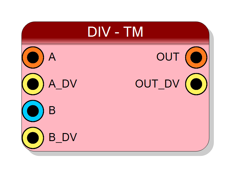
Time-multiplexed fixed-point divider for multi-channel division operations. Performs parallel division across multiple TM phases with configurable formats, optional saturation, and scalar broadcast. Variable latency implementation optimized for resource efficiency.
Introduction
The block performs time-multiplexed division across multiple data streams. On every
rising edge of CLK, when A_DV = 1 and B_DV = 1, the divider computes
$$ \mathrm{OUT}_i(n) = \frac{\mathrm{A}_i(n)}{\mathrm{B}_i(n)}, \quad i = 0, \ldots, \text{TM}-1, $$
where each subscript $i$ represents a different TM phase, and TM is the time-multiplexing factor (4, 8, 16, or 32).
Input A (dividend) is always time-multiplexed. Input B (divisor) can be either
time-multiplexed (phase-by-phase division) or scalar (dividing all A phases by a
single constant divisor).
Division is a complex operation with variable latency depending on operand widths. The component automatically handles the multi-cycle division process for each TM phase.
Pin Description
Input B (divisor), can be time-multiplexed or scalar. If B is TM = YES: Width: (B Integer Bits + B Fractional Bits) × TM Factor Contains TM phases: [B0, B1, …, B(TM-1)] If B is TM = NO: Width: B Integer Bits + B Fractional Bits Single divisor for all A phases
WARNING: Ensure B ≠ 0 to avoid undefined behavior.
Properties
Number of integer bits for input A
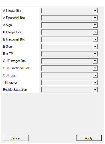
Number of integer bits for input A (dividend). Range: 1-64. Default: 16.Default: 16
Options: 1 2 3 4 5 6 7 8 9 10 11 12 13 14 15 16 17 18 19 20 21 22 23 24 25 26 27 28 29 30 31 32 33 34 35 36 37 38 39 40 41 42 43 44 45 46 47 48 49 50 51 52 53 54 55 56 57 58 59 60 61 62 63 64
Number of fractional bits for input A
Number of fractional bits for input A. Range: 0-64. Default: 0.Default: 0
Options: 0 1 2 3 4 5 6 7 8 9 10 11 12 13 14 15 16 17 18 19 20 21 22 23 24 25 26 27 28 29 30 31 32 33 34 35 36 37 38 39 40 41 42 43 44 45 46 47 48 49 50 51 52 53 54 55 56 57 58 59 60 61 62 63 64
Select if input A is signed or unsigned
Arithmetic type for input A:
- UNSIGNED → Range: [0, 2^(total_bits) - 1]
- SIGNED → Range: [-2^(total_bits-1), 2^(total_bits-1) - 1] Default: SIGNED
Default: SIGNED
Options: UNSIGNED SIGNED
Number of integer bits for input B
Number of integer bits for input B (divisor). Range: 1-64. Default: 16.Default: 16
Options: 1 2 3 4 5 6 7 8 9 10 11 12 13 14 15 16 17 18 19 20 21 22 23 24 25 26 27 28 29 30 31 32 33 34 35 36 37 38 39 40 41 42 43 44 45 46 47 48 49 50 51 52 53 54 55 56 57 58 59 60 61 62 63 64
Number of fractional bits for input B
Number of fractional bits for input B. Range: 0-64. Default: 0.Default: 0
Options: 0 1 2 3 4 5 6 7 8 9 10 11 12 13 14 15 16 17 18 19 20 21 22 23 24 25 26 27 28 29 30 31 32 33 34 35 36 37 38 39 40 41 42 43 44 45 46 47 48 49 50 51 52 53 54 55 56 57 58 59 60 61 62 63 64
Select if input B is signed or unsigned
Arithmetic type for input B:
- UNSIGNED → Non-negative values only
- SIGNED → Two’s complement representation Default: SIGNED
Default: SIGNED
Options: UNSIGNED SIGNED
Select if input B is Time Multiplexed or scalar
Determines if input B is time-multiplexed:
- NO → B is scalar divisor for all TM phases
- YES → B is TM, phase-by-phase division with A Default: NO
Default: NO
Options: NO YES
Number of integer bits for output (typically sum of A+B integer bits)
Number of integer bits for output (quotient). Range: 1-64. Default: 16. Should be sufficient to represent A/B without overflow.Default: 16
Options: 1 2 3 4 5 6 7 8 9 10 11 12 13 14 15 16 17 18 19 20 21 22 23 24 25 26 27 28 29 30 31 32 33 34 35 36 37 38 39 40 41 42 43 44 45 46 47 48 49 50 51 52 53 54 55 56 57 58 59 60 61 62 63 64
Number of fractional bits for output (typically sum of A+B fractional bits)
Number of fractional bits for output. Range: 0-64. Default: 16. Higher values provide more precision in the quotient.Default: 16
Options: 0 1 2 3 4 5 6 7 8 9 10 11 12 13 14 15 16 17 18 19 20 21 22 23 24 25 26 27 28 29 30 31 32 33 34 35 36 37 38 39 40 41 42 43 44 45 46 47 48 49 50 51 52 53 54 55 56 57 58 59 60 61 62 63 64
Select if output is signed or unsigned
Arithmetic type for output:
- UNSIGNED → Output range [0, 2^N - 1]
- SIGNED → Output range [-2^(N-1), 2^(N-1) - 1] Default: SIGNED
Default: SIGNED
Options: UNSIGNED SIGNED
Time Multiplexing factor
Time multiplexing factor (number of parallel phases). Values: 4, 8, 16, 32. Default: 4. Determines how many independent divisions share the hardware.Default: 4
Options: 4 8 16 32
Enable output saturation (otherwise overflow)
Controls overflow behavior:
- YES → Saturate at maximum/minimum representable value
- NO → Wrap-around (modulo 2^N arithmetic) Default: YES.
Strongly recommended for division to handle overflow gracefully.
Default: YES
Options: NO YES
Functional description
The component implements a time-multiplexed divider supporting independent fixed-point formats for each input:
$$ \text{OUT}[i] = \frac{A[i]}{B} \quad \text{or} \quad \text{OUT}[i] = \frac{A[i]}{B[i]}, $$
where:
A[i]→ input A (dividend), phase $i$ (always TM)BorB[i]→ input B (divisor), scalar or TM phase $i$OUT[i]→ output (quotient), phase $i$ (always TM)
Each input has independently configurable:
- Integer bits (1-64)
- Fractional bits (0-64)
- Sign mode (SIGNED/UNSIGNED)
Mathematical background
In fixed-point arithmetic, division requires careful handling of the fractional point:
$$ \frac{\text{Q}{N_A.F_A}}{\text{Q}{N_B.F_B}} = \text{Q}_{(N_A-N_B+F_B).(F_A+N_B-F_B)} $$
To produce an output with $N_{out}$ integer bits and $F_{out}$ fractional bits, the dividend is typically left-shifted by $F_{out}$ bits before division:
$$ \text{OUT} = \frac{A \times 2^{F_{out}}}{B} $$
This ensures the quotient has the desired fractional precision.
Division Algorithm
The component implements a non-restoring division algorithm, which requires approximately $N$ clock cycles to divide an $N$-bit number. For example:
- 16-bit / 16-bit → ~16-20 cycles per phase
- 32-bit / 32-bit → ~32-40 cycles per phase
The exact latency depends on operand values and optimization strategies.
Time Multiplexing
Time multiplexing processes multiple independent divisions through shared hardware:
| Clock cycle | Processing phase |
|---|---|
| 0 | Phase 0 starts: OUT[0] = A[0] / B[0] |
| 1 | Phase 1 starts: OUT[1] = A[1] / B[1] |
| … | … |
| TM-1 | Phase TM-1 starts |
| ~16-40 | Phase 0 completes (depends on width) |
| … | Phases complete sequentially |
Note: Unlike addition/multiplication, division has variable latency that depends on operand widths. The component handles timing automatically.
Scalar Divisor Mode
When B is TM = NO, input B acts as a scalar divisor for all phases:
OUT[0] = A[0] / B
OUT[1] = A[1] / B
...
OUT[TM-1] = A[TM-1] / B
This is useful for:
- Normalization operations
- Scaling by reciprocal (1/B)
- Channel calibration with a reference value
Special Cases and Error Handling
Division by Zero
When divisor B = 0, the behavior is undefined in hardware. The component may:
- Saturate to maximum value (if saturation enabled)
- Return all 1’s
- Assert an error flag (implementation-dependent)
Best practice: Ensure B ≠ 0 through external logic or default values.
Overflow
Overflow can occur when:
- $|A| > |B|$ and insufficient output integer bits
- Example: 1000 / 1 requires output ≥ 10 integer bits for signed
Overflow Handling
The Enable Saturation property controls overflow behavior:
- YES → Output saturates at maximum/minimum representable value
- NO → Output wraps around (modulo arithmetic)
Resource Utilization
Division is resource-intensive compared to other operations:
| Operation | LUTs (typical 16-bit) | Relative cost |
|---|---|---|
| Addition | ~50 | 1× |
| Multiplication | ~200 (LUT) | 4× |
| Division | ~600 | 12× |
Time multiplexing allows sharing this expensive resource across multiple channels.
Timing Considerations
Variable Latency: Division latency varies with:
- Operand widths (larger → slower)
- Sign configuration (signed is slower)
- Dividend/divisor ratio
The component automatically manages flow control, asserting OUT_DV when each
phase completes.
Typical use cases
- Channel normalization in multi-channel systems
- Reciprocal calculation (1/x)
- Ratio metrics in instrumentation
- Adaptive gain control (signal/reference)
- RMS calculation (power/count)
- Fixed-point reciprocal square root preprocessing
Waveform example
Example with TM=4, variable latency ~20 cycles per phase:
Note: Actual timing depends on division latency.