
SR Flip-Flop
Set-Reset flip-flop (SR latch) for bistable storage without clock-dependent data input. Provides asynchronous set and reset control for single-bit state storage. When both SET and RESET are low, the flip-flop holds its current state. Used for control logic, flag storage, and state machines requiring direct state manipulation.
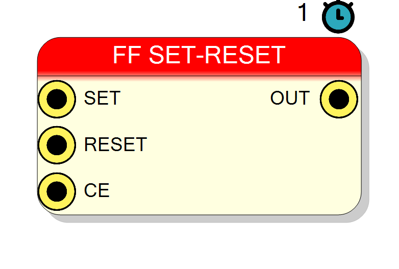
Introduction
This block implements an SR (Set-Reset) flip-flop, a fundamental bistable element that can be directly set to ‘1’ or reset to ‘0’ through dedicated control inputs.
The SR flip-flop operates as follows:
- SET = ‘1’: Output goes to ‘1’ (set state)
- RESET = ‘1’: Output goes to ‘0’ (reset state)
- SET = ‘0’, RESET = ‘0’: Output holds its current value
- SET = ‘1’, RESET = ‘1’: Undefined/forbidden state (typically avoided)
Key characteristics:
- Direct control: No data input required
- Bistable: Two stable states (0 and 1)
- Clock enable for controlled updates
- Latency: 1 clock cycle
- Ideal for control flags and state storage
Pin Description
Clock Enable input (active high).
- CE = ‘1’: SET can control the output
- CE = ‘0’: Output holds current value (SET ignored) Note: RESET operates independently of CE. Default: ‘1’ if left unconnected.
Properties
Functional description
An SR flip-flop is a bistable storage element controlled directly by SET and RESET inputs. Unlike D flip-flops that store data inputs, SR flip-flops are controlled by state commands.
Truth table
| SET | RESET | CE | Behavior |
|---|---|---|---|
| X | 1 | X | OUT = ‘0’ (reset) |
| 1 | 0 | 1 | OUT = ‘1’ (set) |
| 0 | 0 | 1 | OUT = OUT(previous) |
| 0 | 0 | 0 | OUT = OUT(previous) |
| 1 | 1 | X | Undefined (avoid!) |
Note: RESET has priority over SET in this implementation.
Set operation
When SET = ‘1’ and RESET = ‘0’ and CE = ‘1’:
- Output is set to ‘1’ on the next clock edge
- Remains ‘1’ until RESET is asserted
Reset operation
When RESET = ‘1’:
- Output is reset to ‘0’ on the next clock edge
- RESET has priority over SET
- Remains ‘0’ until SET is asserted (with RESET = ‘0’)
Hold operation
When SET = ‘0’ and RESET = ‘0’ and CE = ‘1’:
- Output maintains its current state
- This is the memory function of the flip-flop
Clock enable
The CE input gates the SET operation:
- CE = ‘1’: SET can change the output state
- CE = ‘0’: Output holds current value (SET and RESET ignored)
Note: RESET operates independently of CE (has priority).
Forbidden state
The combination SET = ‘1’, RESET = ‘1’ is typically avoided because:
- Behavior depends on implementation
- May cause race conditions
- Results in unpredictable state when both are released
In this implementation, RESET takes priority, but this state should still be avoided.
Timing
| Property | Latency (clock cycles) |
|---|---|
| SR Flip-Flop | 1 |
State changes occur one clock cycle after SET or RESET is asserted.
SR Flip-Flop vs D Flip-Flop
SR Flip-Flop (this component):
- Direct state control (SET/RESET)
- No data input required
- Ideal for control logic and flags
- Two control inputs instead of one data input
D Flip-Flop:
- Stores data values
- Single data input
- Ideal for data storage and pipelines
- Simpler truth table
Typical use cases
- Control flags: Enable/disable signals in state machines
- Error flags: Set on error condition, cleared by reset
- Handshake protocols: Ready/acknowledge signals
- Interrupt handling: Set on interrupt, cleared when serviced
- Status registers: Single-bit status indicators
- Power management: Wake/sleep state control
- Arbitration logic: Grant/release signals in bus arbiters
Design best practices
- Avoid SET=RESET=1: Design logic to prevent simultaneous assertion
- Priority logic: Understand that RESET has priority in this implementation
- Initialization: Use RESET to establish known power-up state
- Race conditions: Ensure SET and RESET don’t toggle simultaneously
- State machines: SR flip-flops work well for binary state storage
Waveform example
Example showing set, reset, and hold operations:
Sequence:
- OUT = 0 initially
- SET = ‘1’ → OUT = ‘1’ (set)
- SET = ‘0’, RESET = ‘0’ → OUT = ‘1’ (hold)
- RESET = ‘1’ → OUT = ‘0’ (reset)
- SET = ‘1’ → OUT = ‘1’ (set again)