
RF Real -> Complex (Q=0)
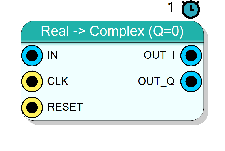
Promotes a single real sample stream to a complex I/Q stream by driving I with the input and forcing Q to zero (Y = IN + j*0). Typical use: feed a real ADC / signal into the complex baseband datapath ahead of a mixer or Hilbert transform.
Introduction
The Real -> Complex block turns a real sample into a complex sample with a zero quadrature component:
OUT_I[n] = IN[n]
OUT_Q[n] = 0
Equivalently the output is OUT = IN + j*0. Data is signed two’s
complement and the width is unchanged.
Pin Description
Properties
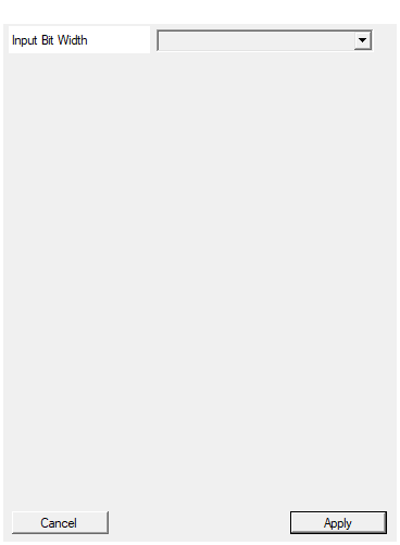
Bit width of the real input sample (signed).
Bit width of the signed real input sample. Range 4 to 32, default 16. The I and Q outputs use the same width.Default: 16
Options: 4 5 6 7 8 9 10 11 12 13 14 15 16 17 18 19 20 21 22 23 24 25 26 27 28 29 30 31 32
Usage
Bit widths
Data is signed two’s complement.
IN: signedInputSizebits.OUT_I: signedInputSizebits (a copy ofIN).OUT_Q: signedInputSizebits, tied to the constant 0.
Notes
A real signal has a two-sided spectrum (its spectrum is conjugate
symmetric). Setting Q = 0 does not remove the negative-frequency image;
to obtain a true one-sided analytic signal follow this block with a
Hilbert transform, or down-convert with a complex mixer + low-pass. Use
this block simply as the type-adapter that lets a real signal enter the
complex I/Q datapath.
Latency and throughput
#pragma HLS PIPELINE II=1: one sample per clock.- 1-clock latency.
- All data ports use the
ap_noneinterface (no ready/valid handshake); the core is free-running (ap_ctrl_none).
Reset
RESET is the HLS synchronous reset (ap_rst).
Typical applications
- ADC / real signal entry point into the complex baseband chain.
- Feed a complex Mixer (real input, complex LO) for down-conversion.
- Front end of a Hilbert transform to build an analytic signal.
Resources & Timing
-
Latency: 1 clock cycle
-
Throughput: 1 sample per clock (II=1)
Zero DSPs: I is a pass-through wire, Q is a tied-off constant. Implemented with Vitis HLS. Free-running core (ap_ctrl_none), no handshake logic.