
Frequency Meter
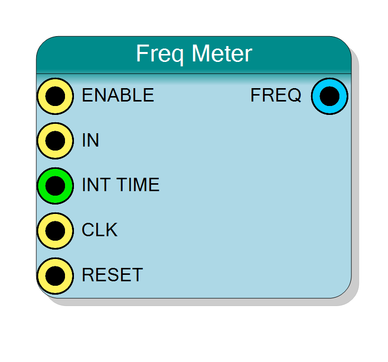
Measures the frequency of an input signal by counting edges over a programmable integration time. Features runtime-configurable measurement period and continuous or gated measurement modes. Configurable counter width from 8 to 64 bits. Outputs frequency count for calculation of Hz.
Introduction
This block measures input signal frequency by counting rising edges over a known time interval (integration time). The measurement principle is simple:
$$ \text{Frequency (Hz)} = \frac{\text{Edge Count}}{\text{Integration Time (s)}} $$
Key features:
- Measures input signal frequency
- Programmable integration time via INTTIME input
- Continuous or gated measurement
- Rising edge counting
- Configurable counter width (8-64 bits)
Operation:
- Set integration time via INTTIME (in system clock cycles)
- Enable measurement via ENABLE=‘1’
- Counter accumulates rising edges on IN during integration period
- FREQ output contains edge count
- Calculate frequency: f = FREQ / (INTTIME / f_CLK)
Pin Description
Measurement enable control.
- ‘1’ = Measurement enabled
- ‘0’ = Measurement disabled, FREQ holds last value
Continuous mode: Keep ENABLE=‘1’ for continuous measurements
Single-shot mode: Pulse ENABLE for single measurement
Behavior:
- ENABLE=‘1’: Starts/continues integration periods
- ENABLE=‘0’: Completes current period if active, then stops
- FREQ updates at end of each integration period while enabled
Default: May connect to ‘1’ if left unconnected (check implementation).
Input signal to measure frequency.
Rising edges on this signal are counted during integration period.
Frequency range:
- Minimum: Limited by integration time and resolution
- Maximum: f_CLK / 2 (Nyquist limit for synchronous counting)
- Typical: DC to f_CLK / 4 for reliable operation
Signal requirements:
- Clean edges (no excessive noise/bouncing)
- If async to CLK: internally synchronized (adds 1-2 cycle latency)
Rising edges are detected synchronously to system clock.
Integration time in system clock cycles.
Type: Unsigned integer (typically 32-bit)
Value: Number of CLK cycles for measurement period
Calculation:
$$ \text{INTTIME} = \text{Desired Time (s)} \times f_{\text{CLK}} \text{ (Hz)} $$
Examples @ 100 MHz clock:
- 1 ms: INTTIME = 100,000
- 10 ms: INTTIME = 1,000,000
- 100 ms: INTTIME = 10,000,000
- 1 s: INTTIME = 100,000,000
Range: 1 to 2^32-1 (practical limit depends on application)
Update: Can be changed between measurements. New value takes effect at start of next integration period.
Default: May connect to global clock frequency parameter.
System clock input.
Provides timing reference for integration timer.
Frequency: Determines measurement resolution and input frequency limit
- Higher f_CLK → Better resolution, higher max frequency
- Typical: 50-200 MHz for general applications
Must be stable and accurate for precise frequency measurement.
Default: Connects to global clock if left unconnected.
Synchronous reset (active high).
- ‘1’ = Reset frequency meter: counters to 0, stop integration
- ‘0’ = Normal operation
Resets both integration timer and edge counter. FREQ output cleared to 0.
Default: Connects to global reset if left unconnected.
Frequency measurement output (edge count).
Type: Unsigned integer
Width: Configured by Bit Number property (8-64 bits)
Value: Number of rising edges counted during last integration period
Update: Updates at end of each integration period (when ENABLE=‘1’)
Calculation to Hz:
$$ f_{\text{IN}} \text{ (Hz)} = \text{FREQ} \times \frac{f_{\text{CLK}}}{\text{INTTIME}} $$
Hold behavior: Holds last value when ENABLE=‘0’ or after reset
Overflow: If input frequency too high, counter may overflow. Choose appropriate Bit Number to prevent overflow:
$$ \text{BitNumber} \geq \log_2(f_{\text{IN,max}} \times \text{Integration Time}) $$
Registered output, stable and glitch-free.
Properties
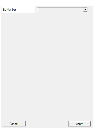
Set the number of bit used in the timer accumulator
Number of bits in the frequency counter.
Available values: 8, 16, 24, 32, 40, 48, 56, 64
Determines:
- Maximum count = 2^BitNumber - 1
- Maximum measurable frequency (before overflow)
- Width of FREQ output
Sizing calculation:
$$ \text{Max Count} = f_{\text{IN,max}} \times \frac{\text{INTTIME}}{f_{\text{CLK}}} $$
$$ \text{Required Bits} = \lceil \log_2(\text{Max Count} + 1) \rceil $$
Examples:
| f_IN max | Integration | f_CLK | Max Count | Bits Needed |
|---|---|---|---|---|
| 10 kHz | 1 s | 100 MHz | 10,000 | 14 bits |
| 1 MHz | 1 s | 100 MHz | 1,000,000 | 20 bits |
| 10 MHz | 1 s | 100 MHz | 10,000,000 | 24 bits |
| 100 MHz | 1 s | 100 MHz | 100,000,000 | 27 bits |
| 1 MHz | 10 ms | 100 MHz | 10,000 | 14 bits |
Recommendation: Use 32 bits for most applications (provides wide margin and negligible resource impact on modern FPGAs).
Default: 32
Options: 8 16 24 32 40 48 56 64
Functional description
The frequency meter operates as a gated counter with automatic integration time control:
Measurement principle
- Integration timer: Counts system clock cycles from 0 to INTTIME-1
- Edge counter: Counts rising edges on IN during integration
- Output: FREQ contains edge count at end of integration
- Auto-restart: Begins new measurement period when enabled
Timing sequence
t=0: Start integration period
t=0 to INTTIME: Count rising edges on IN
t=INTTIME: Latch count to FREQ output, restart if ENABLE='1'
Frequency calculation
Given:
- INTTIME = Integration time in clock cycles
- f_CLK = System clock frequency (Hz)
- FREQ = Measured edge count
$$ \text{Integration Time (s)} = \frac{\text{INTTIME}}{f_{\text{CLK}}} $$
$$ \text{Input Frequency (Hz)} = \frac{\text{FREQ}}{\text{INTTIME}} \times f_{\text{CLK}} $$
Simplified formula
$$ f_{\text{IN}} = \text{FREQ} \times \frac{f_{\text{CLK}}}{\text{INTTIME}} $$
Example calculation
Scenario:
- System clock: f_CLK = 100 MHz
- Integration time: INTTIME = 100,000,000 (1 second @ 100 MHz)
- Measured count: FREQ = 1,234,567
Calculation:
$$ f_{\text{IN}} = 1,234,567 \times \frac{100,000,000}{100,000,000} = 1,234,567 \text{ Hz} = 1.234567 \text{ MHz} $$
Measurement accuracy
Resolution:
$$ \text{Resolution} = \frac{f_{\text{CLK}}}{\text{INTTIME}} = \frac{1}{\text{Integration Time (s)}} $$
Examples @ 100 MHz clock:
| INTTIME | Integration Time | Resolution | Max Freq (32-bit) |
|---|---|---|---|
| 1,000 | 10 µs | 100 kHz | 429 MHz |
| 10,000 | 100 µs | 10 kHz | 42.9 MHz |
| 100,000 | 1 ms | 1 kHz | 4.29 MHz |
| 1,000,000 | 10 ms | 100 Hz | 429 kHz |
| 10,000,000 | 100 ms | 10 Hz | 42.9 kHz |
| 100,000,000 | 1 s | 1 Hz | 4.29 kHz |
Tradeoff:
- Longer integration time → Better resolution, slower updates
- Shorter integration time → Faster updates, coarser resolution
Timing diagram
The diagram shows:
- Integration timer counts 0 to INTTIME-1 (0 to 4)
- Rising edges on IN counted during integration
- FREQ updated at end of each integration period
- First period: 6 edges counted
- Second period: 4 edges counted
- Continuous measurement when ENABLE=‘1’
Typical use cases
- RPM measurement: Measure motor/encoder speed
- Signal frequency verification: Check oscillator/PLL output
- Event rate monitoring: Measure packet rate, interrupt rate
- Vibration measurement: Frequency of vibrating sensors
- Audio frequency detection: Measure audio signal frequency
- Communication link monitoring: Check data rate
- Sensor validation: Verify sensor output frequency
Design considerations
Choosing integration time
Factors to consider:
- Required resolution: Longer time = finer resolution
- Update rate: Shorter time = faster updates
- Frequency range: Must count enough edges for accuracy
- Counter size: Ensure counter doesn’t overflow
Rules of thumb:
- Integration time ≥ 10× input period (for 10% accuracy)
- Integration time ≥ 100× input period (for 1% accuracy)
- Integration time ≥ 1000× input period (for 0.1% accuracy)
Integration time examples
To measure 1 kHz signal with 1% accuracy:
- Need ≥100 cycles of 1 kHz = 100 ms integration time
- @ 100 MHz clock: INTTIME ≥ 10,000,000
To measure 1 MHz signal with 0.1% accuracy:
- Need ≥1000 cycles of 1 MHz = 1 ms integration time
- @ 100 MHz clock: INTTIME ≥ 100,000
Counter overflow prevention
Maximum measurable frequency before overflow:
$$ f_{\text{max}} = \frac{2^{\text{BitNumber}} - 1}{\text{Integration Time (s)}} $$
Example (32-bit counter, 1s integration @ 100 MHz):
$$ f_{\text{max}} = \frac{2^{32} - 1}{1 \text{ s}} = 4.29 \text{ GHz} $$
Usually counter size is not the limitation - system clock frequency is.
Input frequency limits
Synchronous counting limits:
- Maximum input frequency ≈ f_CLK / 2 (Nyquist)
- For reliable counting: f_IN < f_CLK / 4
For higher frequencies:
- Use asynchronous counter (if available)
- Use prescaler before frequency meter
- Increase system clock frequency
Measurement modes
Continuous mode (ENABLE always ‘1’):
- Continuous back-to-back measurements
- FREQ updates every integration period
- Good for monitoring varying frequencies
Gated mode (ENABLE toggled):
- Single measurement per ENABLE pulse
- ENABLE=‘1’ starts measurement
- ENABLE=‘0’ stops after completing current period
- Good for triggered measurements
INTTIME as property vs input
This component uses INTTIME as input port:
- Runtime programmable
- Can vary measurement time
- Connect to constant for fixed integration time
- Connect to register for software control
Typical usage:
- Connect to constant parameter for fixed time
- Connect to CPU register for adjustable time
- Calculate constant: INTTIME = Desired_Time(s) × f_CLK