
ALU - ADDER
Configurable binary adder with optional pipeline register and overflow protection. Supports signed or unsigned integer addition with selectable input width (2-256 bits) and optional extra output bit to prevent overflow.
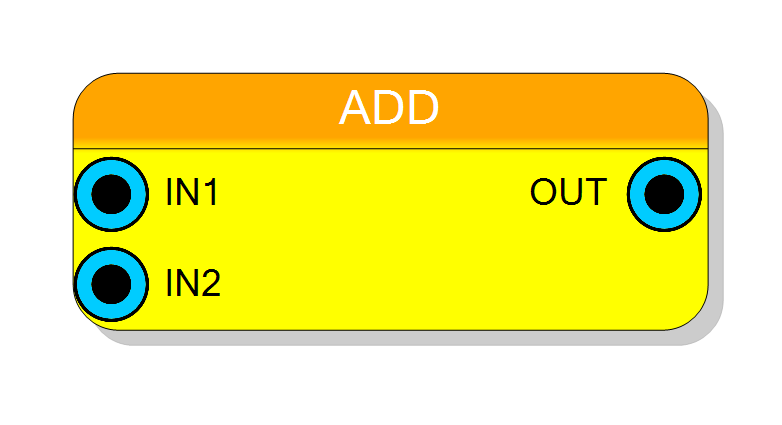
Introduction
The adder performs binary addition of two input operands IN1 and IN2,
producing the sum on output OUT.
$$ \mathrm{OUT} = \mathrm{IN1} + \mathrm{IN2} $$
The component supports both signed and unsigned arithmetic according to the Input sign property. An optional pipeline register can be enabled to improve timing at the cost of one clock cycle latency.
Pin Description
Sum output. Width depends on Output Size property:
- SAME INPUT: same as Input bits
- EXTRA BIT: Input bits + 1
Properties
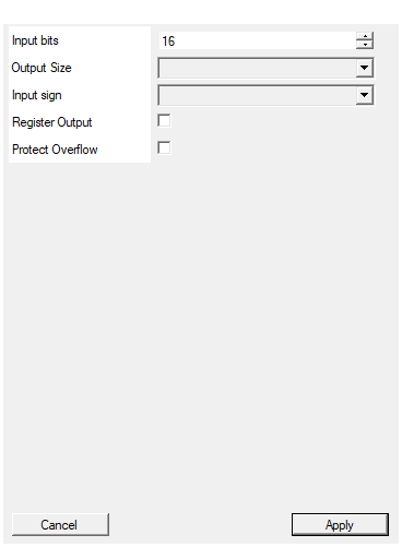
Set the number of bits of the input
Number of bits for both input operandsIN1 and IN2.
Range: 2 – 256.
Determines the width of the adder datapath.
Default: 16
Range: 2 – 256
Select if the output should have one extra bit to avoid overflow in the result
Controls output bit width:
- SAME INPUT: Output width equals Input bits (overflow wraps around)
- EXTRA BIT: Output width is Input bits + 1 (carry-out included)
Default: SAME INPUT
Options: SAME INPUT EXTRA BIT
Select the sign/unsign of the input
Selects arithmetic type for inputs and output:
- UNSIGNED: Non-negative integers, range [0, 2^N-1]
- SIGNED: Two’s-complement, range [-2^(N-1), 2^(N-1)-1]
Default: UNSIGNED
Options: UNSIGNED SIGNED
Enable one pipeline stage adding a register. Improve system timing but increase pipeline delay from 0 to 1 clock cycle
Enables output pipeline register.
- False: Combinatorial output (0 latency)
- True: Registered output (1 cycle latency, improved timing)
Default: False
Enable overflow protection logic. The overflow logic will saturate output to maximum value in overflow condition. This option, if enabled, negatively impact on system timing.
Enables saturation logic on overflow.
- False: Arithmetic wraps around on overflow
- True: Output saturates to maximum value (impacts timing)
Default: False
Functional description
The adder implements a combinatorial or registered addition:
$$ y = a + b $$
where:
a→IN1b→IN2y→OUT
Output width options
The Output Size property controls the output bit width:
- SAME INPUT: Output has the same width as inputs (wrap-around on overflow)
- EXTRA BIT: Output has one extra bit to accommodate the carry-out
Overflow protection
When Protect Overflow is enabled, the output saturates to the maximum representable value instead of wrapping around. This option impacts timing performance.
Latency
The component latency depends on the Register Output property:
| Register Output | Latency (clock cycles) |
|---|---|
| Disabled | 0 (combinatorial) |
| Enabled | 1 |
Typical use cases
- Basic arithmetic operations in DSP pipelines
- Accumulation and counting circuits
- Address calculation
- Fixed-point arithmetic