
FFT Average
Coherent spectrum averager for the sequential FFT streams: accumulates a programmable power-of-two number of complete spectra bin by bin and streams the averaged spectrum out in the same sequential format. The number of averages is a runtime input, the output can keep the input width (rounded) or grow 16 fractional bits for an exact fixed point average. Double buffered, so no input spectrum is ever lost while the result streams out.
Introduction
Averaging $M$ spectra of the same stationary signal reduces the variance of the noise floor by $M$ (i.e. $10\log_{10} M$ dB on power spectra of uncorrelated noise) while leaving coherent spectral lines untouched:
$$ \bar{X}[k] = \frac{1}{2^{NAVG}}\sum_{m=0}^{2^{NAVG}-1} X_m[k], \quad k = 0, 1, \ldots, N-1 $$
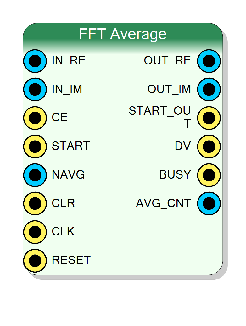
The block consumes the sequential spectrum bursts produced by the FFT,
FFT Windowed and FFT TM Triggered blocks: one complex bin per
CE-gated clock on IN_RE / IN_IM, with START marking bin 0 of every
frame. It adds each incoming spectrum into a BRAM accumulator (one complex
accumulator per bin) and, when $2^{NAVG}$ complete spectra have been
summed, streams the averaged spectrum out as the same kind of burst:
START_OUT pulses on bin 0, DV_OUT is high for the $N$ output bins.
The accumulator is double buffered (ping-pong): while the finished average is being read out (and its memory cleared row by row, ready for reuse), the other buffer is already accumulating the next round, so the averager never drops an input spectrum.
NAVG is a runtime input: the log2 of the number of spectra to
average (e.g. 10 → 1024 spectra). It can be driven by a register and
changed on the fly; the value is latched at the start of every round, so a
change takes effect on the next round. Values above the compile-time Max
averages budget are clamped.
Pin Description
Properties
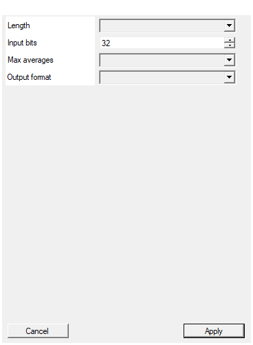
Number of bins of one FFT frame. Must match the Length of the FFT block feeding this averager.
Number of bins N of one spectrum (64 .. 65536, power of 2). Must match the Length of the FFT block feeding the averager.Default: 1024
Options: 64 128 256 512 1024 2048 4096 8192 16384 32768 65536
Width of the IN_RE / IN_IM samples (the FFT blocks output 32 bit).
Width of IN_RE / IN_IM (8..48, signed). The FFT blocks output 32 bit, so 32 chains them directly.Default: 32
Range: 8 – 48
Largest number of spectra the runtime NAVG input can request. Sizes the accumulator BRAM: each bin stores InputBits + log2(MaxAverages) bits per component, twice (ping-pong).
Largest number of spectra the runtime NAVG input can request (2 .. 65536, power of 2). Sizes the BRAM accumulators: each of the 2 x Length rows stores 2 x (InputBits + log2(MaxAverages)) bits. Keep it as small as your application needs to save BRAM.Default: 1024
Options: 2 4 8 16 32 64 128 256 512 1024 2048 4096 8192 16384 32768 65536
Same as input (rounded): OUT is InputBits wide, average rounded half-up. Fixed point (+16 fractional bits): OUT is InputBits+16 wide and EXACT, the 16 extra LSBs are fractional bits (same integer scaling as the input).
- Same as input (rounded): OUT is InputBits wide, average rounded half-up.
- Fixed point (+16 fractional bits): OUT is InputBits+16 wide and exact; the 16 extra LSBs are fractional bits (Q x.16 with the input integer scaling).
Default: Same as input (rounded)
Options: Same as input (rounded) Fixed point (+16 fractional bits)
Chaining from the FFT blocks
OUT_RE→IN_RE,OUT_IM→IN_IMFIRST(orFRAME_START/START_OUTof the source) →STARTDV→CE
Leaving CE unconnected ties it to ‘1’ (every clock carries a bin);
leaving NAVG unconnected gives $2^0 = 1$, i.e. the block passes each
spectrum through unchanged.
Output scaling
With $M = 2^{NAVG}$ accumulated spectra the accumulator holds $\sum X_m[k]$, which is $NAVG$ bits wider than the input. The Output format property selects how the division by $M$ is returned:
- Same as input (rounded) —
OUTis InputBits wide: $\bar{X} = \left\lfloor (\sum X_m + 2^{NAVG-1}) / 2^{NAVG}\right\rfloor$ (round half-up). No overflow is possible: the average of $M$ values is bounded by the input range. - Fixed point (+16 fractional bits) —
OUTis InputBits + 16 wide and exact: $\bar{X} \cdot 2^{16} = \sum X_m \cdot 2^{16-NAVG}$. The 16 extra LSBs are fractional bits; the integer part keeps the input scaling, so downstream Fixed P. blocks can consume it directly as a Q(InputBits).16 value.
Round lifecycle
STARTmarks bin 0; everyCEclock accumulates one bin.AVG_CNTshows in realtime how many complete spectra of the current round have been accumulated (0 … $2^{NAVG}-1$) — use it for progress.- After the last bin of spectrum $2^{NAVG}$, the buffers swap and the
averaged spectrum streams out ($N$ contiguous clocks,
START_OUT+DV_OUT,BUSYhigh for the whole burst). Each memory row is cleared right after it is read. - Accumulation of the next round proceeds meanwhile in the other buffer.
CLR (synchronous, one clock is enough) discards the accumulation in
progress and restarts the round from zero — use it after retuning, or to
align the averaging window to an external event. The global RESET does
the same.
Limits
- The frame length of the source FFT must match Length (the block
tracks bins modulo $N$ and resynchronizes on every
START). - With
NAVG = 0(passthrough) and perfectly gapless back-to-back input frames the output burst ($N$ clocks) cannot keep up with the input frame rate; a round that completes while the previous burst is still streaming is dropped (accumulation itself never stops). Any $NAVG \geq 1$ cannot hit this.
Resources
Two BRAM buffers of $N$ rows, each row $2,(\text{InputBits} + \log_2 \text{MaxAverages})$ bits. E.g. Length 1024, InputBits 32, Max averages 1024: 2 × 1024 × 84 bit ≈ 5 BRAM18. No DSP, no HLS: pure VHDL.
Verified with a self-checking GHDL regression (3 configurations, 488 checks: rounding on negative accumulations, CE gaps, buffer reuse across rounds, mid-round CLR, runtime NAVG change and clamp, DV/START_OUT/BUSY framing, AVG_CNT progress).