

State Bodies, Ports and Variables
What can be drawn inside the body of a state: State Ports (the machine inputs and outputs), State Variables (registers shared by the states), the STATE ACTIVE / STATE ENTERED sources, which components are allowed, and the clock and reset rules of the bodies.
The Body of a State
Every state owns one body page. The body describes:
- the value of the machine outputs while the machine is in this state;
- the EXIT CONDITION of every transition leaving the state (see State Machine Editor);
- any logic needed to compute them: gates, comparators, multiplexers, counters, timers, memories… - the same palette as any other page, minus the few blocks listed in Allowed and hidden blocks below.
When a body is shown, the palette (Blocks panel) adds the state machine blocks and hides what cannot be used there. Search “state” to list them:
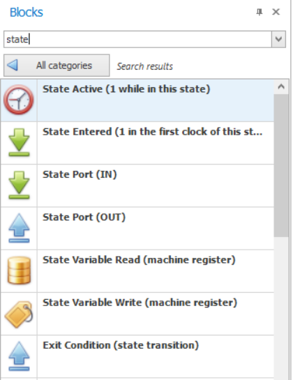
Figure 1: the state machine blocks of the palette
The canvas right-click menu of a body also offers Exit Condition…, State Active, State Entered, State Variable Read… and State Variable Write…:
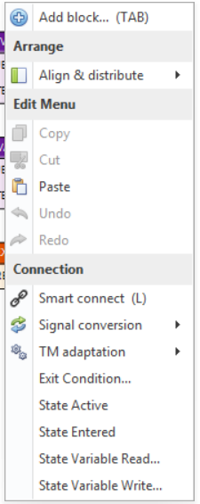
Figure 2: canvas right-click menu on a state body
State Ports
A State Port is an input or output of the whole machine; it becomes a pin of the machine block. State Ports are the normal schematic port blocks, shown on state pages with the caption STATE PORT.
One declaration, many states
Ports are declared once per machine and reused in any state: the same output LED
can be driven by a constant 1 in one state and by a blinking signal in another; the
same input BTN can be read by every state. The declarations are listed in the
STATE PORTS panel, under the palette, while a body of the machine is shown:
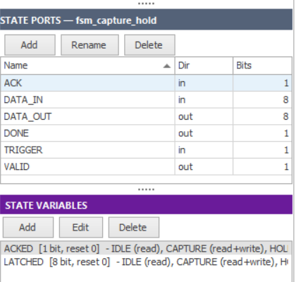
Figure 3: STATE PORTS (name, direction, width) and STATE VARIABLES panels. The divider between the two lists can be dragged
| Panel action | Effect |
|---|---|
| Add | Declares a new port: direction, name, signal type (std_logic_vector or the TM type) and width. A declared port does not need to be placed yet. |
| Rename (or double-click a row) | Renames the port in the machine and in every body where it is placed. |
| Delete | Removes the declaration; if the port is placed in some states, the list of states is shown for confirmation and the blocks are removed too. |
| Tooltip on a row | The states that use the port, or not placed yet. |
| Drag rows onto the body | Places the ports at the drop point (several rows at once are stacked). |
Placing a State Port
- palette State Port (IN) / State Port (OUT): a chooser lists the declared ports of that direction plus <New State Port…>; a new port is asked with three short dialogs (name, type, width);
- drag a row from the STATE PORTS panel;
- right-click a pin of a component and choose Connect to new State Port or Connect to existing State Port: the port block is placed next to the pin, at the pin height, and wired. A new port takes the pin name, direction, type and width (the name can be edited). With several pins selected, one port per pin is proposed.
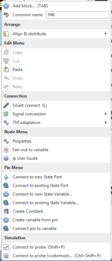
Figure 4: pin right-click menu on a state body: State Port and State Variable commands
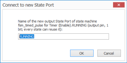
Figure 5: naming the new port created from a pin
Double-click or F2 on a placed State Port renames the port machine-wide.
Rules
- An input port may be placed any number of times in a body.
- An output port can have only one driver per state: placing a second block of the same output on a page selects the existing one instead, and wiring a second driver is refused.
- A state whose body does not drive an output gives 0 on that output.
- Same name means same port: direction, type and width must agree in every state.
- Reserved names:
CLK,CLOCK,RESET,STATE_OUT,TRANSITION_OUT,STATE_ACTIVE,STATE_ENTERED, the clock / reset service names of the board (GlobalClock,GlobalReset, …) and the prefixesXL_,SVR_,SVW_,SVE_.
STATE ACTIVE and STATE ENTERED
Two 1-bit source blocks (teal header) available only on bodies:
| Block | Value |
|---|---|
| STATE ACTIVE | 1 during every clock in which the machine is in this state. |
| STATE ENTERED | 1 during the first clock spent in this state: after every transition into it, a self-loop included, and for the initial state during RESET and the first clock after it. |
Because every body runs all the time (see Clock and reset below), these are the tools to make a block of a body behave “only while I am active” or “restart on entry”:
- enable a counter / timer with STATE ACTIVE;
- clear or restart it with STATE ENTERED.
Entry clock rule. A register cleared by STATE ENTERED shows its cleared value only from the second clock in the state; during the entry clock it still holds the old value. An exit condition that reads such a counter must therefore be qualified with
AND NOT STATE ENTERED(for examplecount >= N AND NOT STATE ENTERED). The Timed pulse example shows the idiom.
Several blocks of the same kind on one page are allowed (they are the same signal). They have no settings: a double-click only explains them.
State Variables
A State Variable is a register of the machine, shared by all its states: one
state writes it, any state reads it. It is the way to pass a value from one state to
the next (a captured sample, a counter, a flag). State Variables are listed in the
STATE VARIABLES panel as name [bits, reset] - usage.
State Variables are not the page-scoped Variable (Read) / Variable (Write) blocks of normal pages. Those named wires can still be used inside a body, but they exist only on that page.
Declaring and editing
Add and Edit (or double-click a row) open the same dialog: Name, Width
(1 to 64 bits) and Reset value (decimal, 0x... or 0b...). Problems are shown in
red below the fields and OK stays disabled until they are fixed.
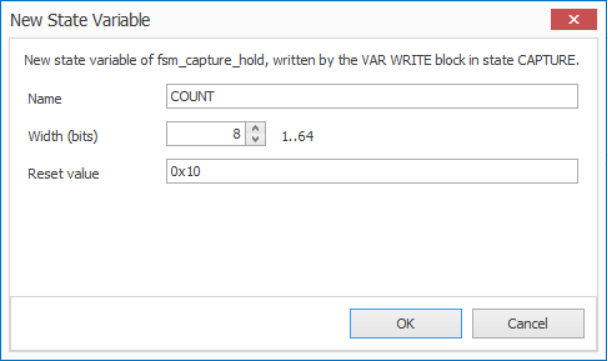
Figure 6: declaring a State Variable
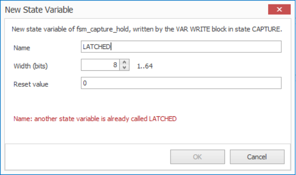
Figure 7: a name already used by another variable is refused
- Changing the name renames every VAR READ / VAR WRITE block of the variable.
- Changing the width resizes every block of the variable in every state. Wires are kept; a wire whose other end does not have the new width turns red and is reported in the Compiler Output, so you can fix it. If the variable is wired somewhere, the states concerned are listed and confirmation is asked.
- Changing only the reset value changes nothing in the diagrams.
- Delete removes the declaration only; blocks still using it become invalid and are reported until you delete or rebind them.
VAR READ and VAR WRITE blocks
| Block | Pins | Meaning |
|---|---|---|
| VAR READ <v> | output = value | The current value of the register. Any number of blocks, in any state. |
| VAR WRITE <v> | VALUE (input, width of v), WRITE (1-bit input) | Loads VALUE into the register at the clock edge while the state is active and WRITE = 1. |
WRITE left unconnected = write on every clock while the state is active. Only one VAR WRITE per variable per state is allowed; several states may write the same variable (only one state is active at a time).
Ways to place them:
-
palette State Variable Read / Write (machine register) or canvas right-click State Variable Read… / Write…: a chooser lists the variables, with <New State Variable…> first (it opens the declaration dialog and places the block of the new variable). Variables already written in this state are marked already written in this state and cannot be chosen for a second VAR WRITE;
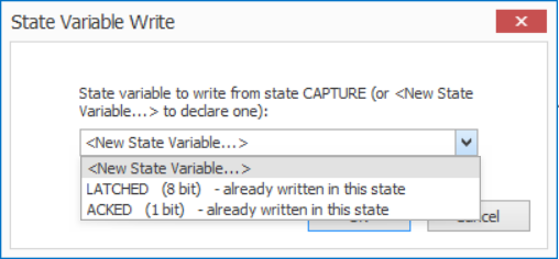
Figure 8: VAR WRITE chooser with the <New State Variable…> entry
-
drag a row of the STATE VARIABLES panel onto the body: a small menu asks Read <v> or Write <v> (Write is disabled when the state already writes the variable). Hold Shift while dropping to place a VAR WRITE directly, Ctrl for a VAR READ. Several rows dropped together become VAR READs (Shift: VAR WRITEs);
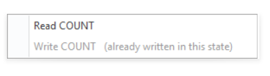
Figure 9: dropping a variable on a body
-
right-click a pin (or a wire) and choose Connect to new State Variable… or Connect to existing State Variable…: an input pin gets a VAR READ on its left, an output pin (or the source of the wire) a VAR WRITE on its right, wired to VALUE. A free VAR WRITE of the same variable already on the page is reused. The whole gesture is one undo step.
To change the variable of a placed block: double-click it, press F2, or right-click it and choose Change State Variable…. The block is replaced in place and its wires are kept.
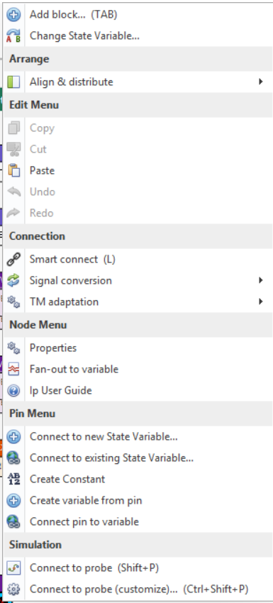
Figure 10: right-click on a VAR READ: Change State Variable… and the pin commands
Timing
- A value written in a state is seen by the next state from its first clock (the write happens on the same clock edge that changes state).
- A state that reads and writes the same variable reads the old (registered) value.
- RESET loads the reset value; a variable that nobody writes keeps its value.
- To show a variable outside the machine, wire a VAR READ to an output State Port.
Clock and Reset
- Every body runs on the machine clock (
CLKpin of the machine block): every clock pin of every block inside the machine, connected or not, is driven by it. The built-in Clock block is therefore not available in bodies. - Every reset pin left unconnected inside a body is driven by the machine
RESET. A reset pin you wire explicitly keeps your signal. - Every body is instantiated and clocked all the time, whatever the current state. A timer placed in a state keeps counting while the machine is elsewhere and is not cleared on entry unless you use STATE ACTIVE / STATE ENTERED. Only the outputs are selected by the current state, and the EXIT CONDITIONs are only looked at while their state is current.
Allowed and Hidden Blocks
Everything that is pure logic or local processing is allowed: gates, comparators, multiplexers, flip-flops, edge detectors, timers, counters, delays, FIFO / RAM / ROM, shapers, triggers, math, the page-scoped Variable blocks, the Signal Generator…
The following are hidden from the palette on a body, and refused on paste and at compile:
- blocks that create a memory-mapped component (registers, register files, components with a software endpoint such as oscilloscopes, lists, spectra);
- board I/O: board pins, LEMO, analog inputs / outputs, digitizer and readout blocks, serial links, PLLs;
- the Clock block and components that need a dedicated clock (TDC 500ps and its controller, TDC Syncronous, Time over Threshold (Digital)); the Timestamp block is allowed only with Clock Source = Board;
- nested sub-designs and state machines (new or legacy).
Keep these on the parent page and connect them to the machine through its State Ports.
Related Documentation
- State Machine Editor
- Generated HDL, Validation and Limitations
- State Machine Examples
- Pins, Variables & Registers Workflow