PUR (SIMPLE)
Single–channel pile-up rejector (PUR) with programmable dead-time and guard-time. It ensures that only isolated events whose inter-arrival time Δt ≥ LENGTH are accepted, providing optional parallel re–arming through the PARAL input.
Introduction
What the block does
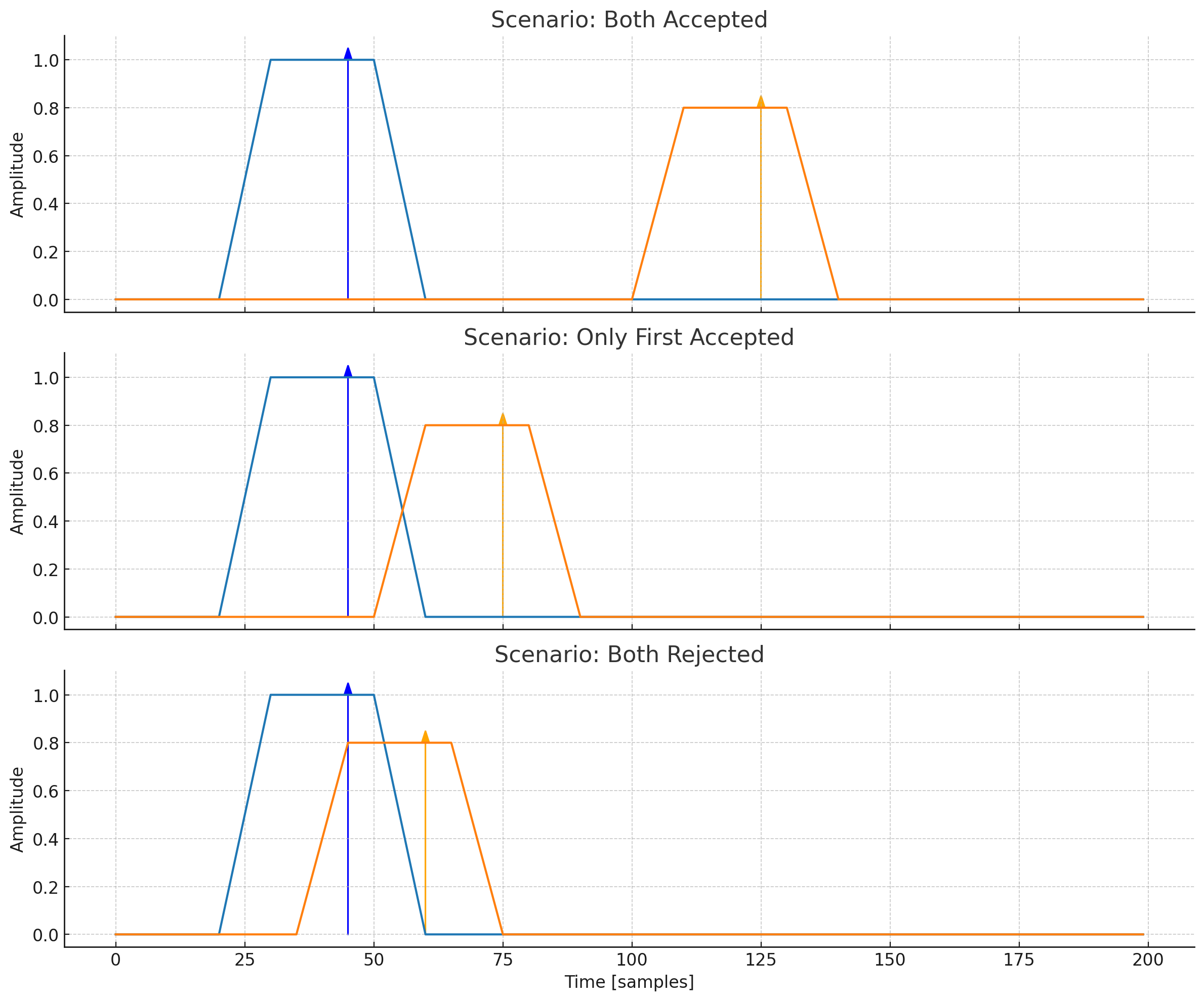
PUR_SIMPLE is a pile-up rejector: it examines the time distance between consecutive trigger pulses (TRIGGER_IN) and discards events that arrive too close to a previously accepted one.
Two programmable windows are implemented:
- Dead-Time (
DLENGTH) – a strict inhibit period in which every incoming pulse is always rejected (hard dead-time). - Guard-Time (
LENGTH) – a softer extension that still keeps the PUR busy (event rejected) but allows the next clean event to be accepted if no further pile-up occurs.
The block can optionally work in parallelisable mode (PARAL = ’1’), which immediately resets the windows every time a new pile-up candidate is detected, emulating a “sliding” dead-time behaviour.
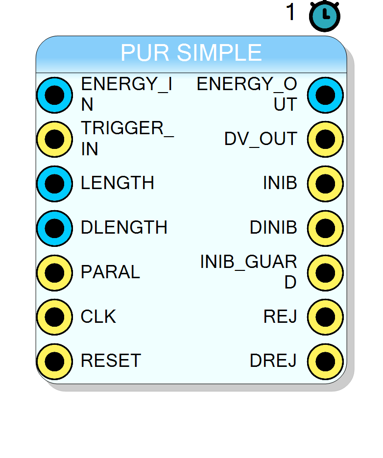
Pin Description
BITSIZE (default = 16).Sampled on the rising edge of
CLK only when TRIGGER_IN = '1'.
ENERGY_IN.A rising edge starts the inter-arrival time measurement.
Must satisfy a single-clock high-pulse protocol.
When
inib_counter3 (dead-time) expires, the FSM keeps INIB high
for LENGTH additional clocks before forwarding the stored event.
Defines the strict period in which all incoming triggers are rejected (
DINIB = 1).
•
0 – Non-parallel: windows are fixed after the first pulse.•
1 – Parallel: windows are re-loaded every time a new pulse arrives during inhibition, emulating a sliding dead-time.
Must be common to every TM block within the design.
Clears the FSM to State 0 and forces all outputs low.
INIB.Valid only when
DV_OUT = '1'.
ENERGY_OUT.Asserted for one clock cycle for every accepted event.
Can be used by downstream logic to disable integrators or shapers.
INIB).High only during the strict dead-time
DLENGTH.
DINIB has already elapsed but residual pulses are still pending.
DLENGTH but before the current guard-time has finished.
DLENGTH.Useful for estimating pile-up statistics.
Properties
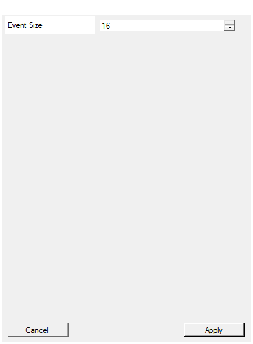
This parameters sets the number of bits for the Input and Output Event size
Defines the bit-width of bothENERGY_IN and ENERGY_OUT.Accepted range: 1 – 32 (synthesis must fit the target device).
Higher
BITSIZE increases resource usage on the DSP and routing network but allows larger ADC dynamic range.
Default: 16
Functional description
Let
$t_i$ be the arrival time of the i-th trigger pulse, $\Delta t_i = t_i - t_{i-1}$ the inter-arrival time, $T_D$ the dead-time (DLENGTH), $T_G$ the guard-time (LENGTH).
The PUR finite-state machine (FSM) behaves as follows:
-
State 0 – Idle
Waits for the rising edge of TRIGGER_IN (ddvin). When detected, it
sets
$$ \text{inibCounter2} \leftarrow T_G + T_D,\qquad \text{inibCounter3} \leftarrow T_D $$
and raisesINIBandDINIB. -
State 1 – Dead-Time
DINIBstays high for exactlyDLENGTHclocks.
Any pulse within this window setsDREJ = 1.
If PARAL = ’1’, the counters are re-loaded so that the dead-time slides with every new pile-up; otherwise the counters just decrement. -
State 2 – Guard-Time
DINIBis cleared,INIBmay remain high until the residual part
ofinib_counter2expires.
The first clean pulse that appears after guard-time is accepted:
its energy word is forwarded toENERGY_OUT,DV_OUTis asserted for one clock, and the FSM returns to State 0.
Any pulse arriving whileINIBis still high but outsideDINIBraisesREJ = 1.
Mathematical model
An event i is accepted if
$$\Delta t_i \ge T_D + T_G$$
in non-parallel mode, or
$$\Delta t_i \ge T_D \quad\text{and no other trigger inside }[t_{i-1},;t_i)$$
in parallel mode (sliding dead-time).
Timing
- Latency:
The data word captured at the end of guard-time is delivered toENERGY_OUTwithDV_OUT = 1after 1 clock cycle thanks to thePIPELINE II=1directive. - Throughput:
One accepted event per clock when the windows are inactive.
Typical use case
PUR_SIMPLE is commonly placed after a leading edge discriminator in gamma-ray or particle spectroscopy chains to guarantee the purity of the energy spectrum by rejecting pile-up events that would bias amplitude estimation.