
MCA HLS
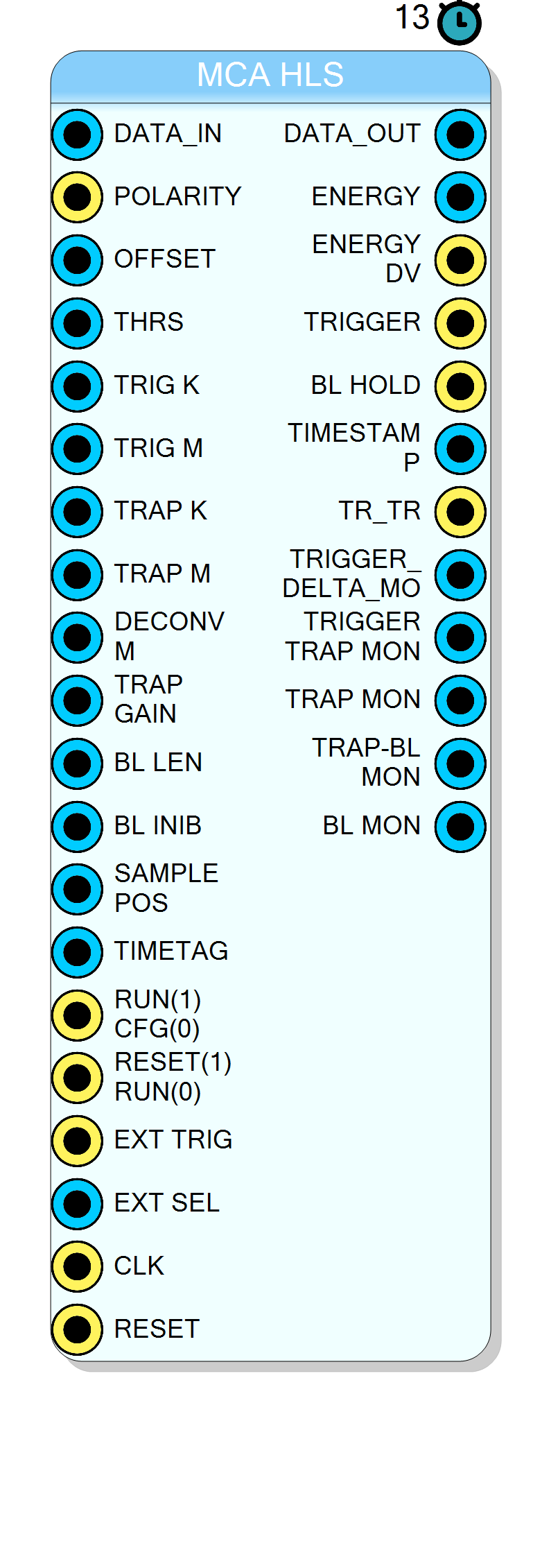
Complete Multi-Channel Analyzer (MCA) processing chain implemented in HLS. Integrates fast trapezoidal trigger, slow trapezoidal energy shaper, baseline restorer, and energy sampler in a single high-performance block.
Introduction
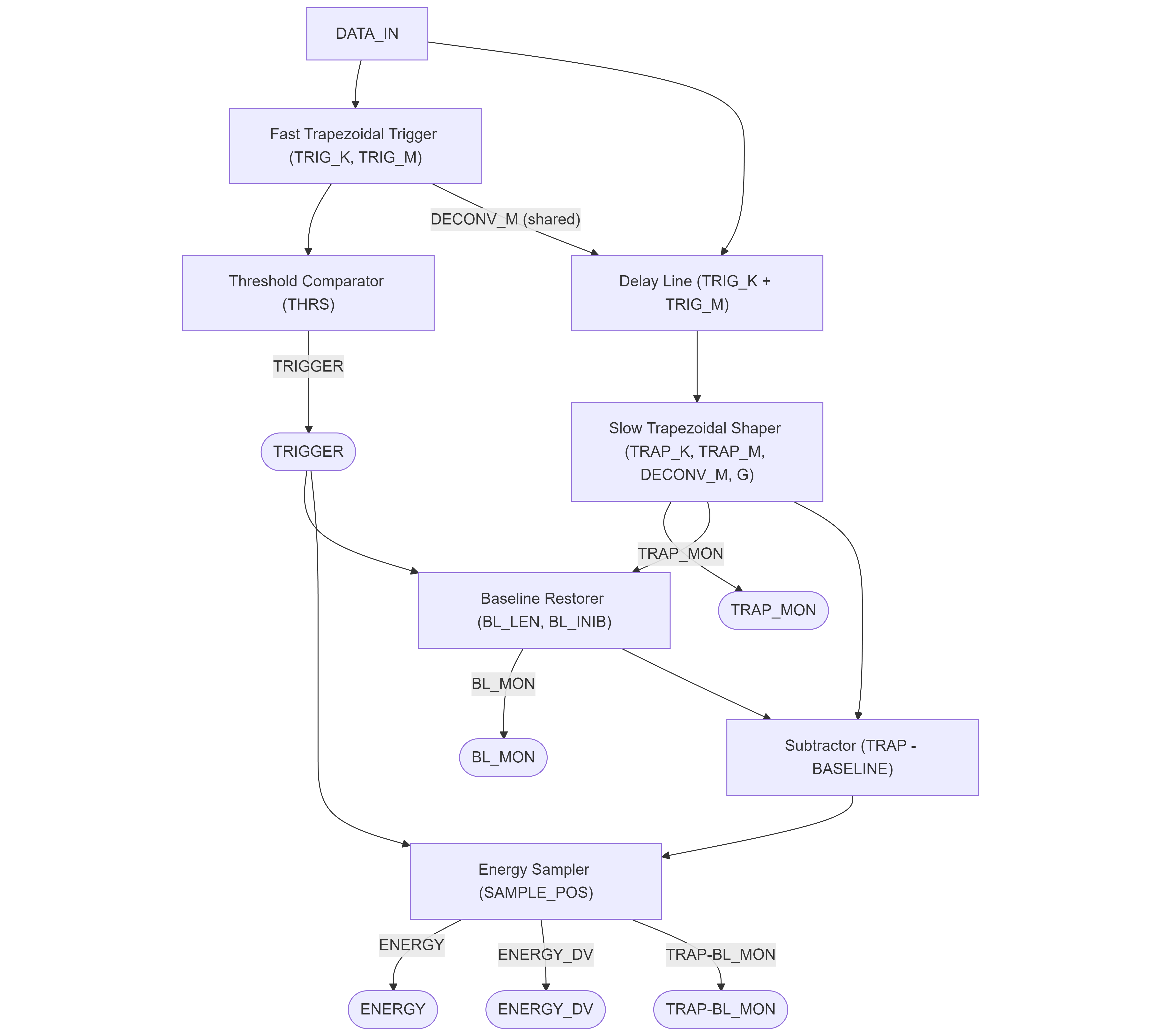
The MCA HLS block implements a complete digital pulse processing chain for Multi-Channel Analyzer applications. It combines four key processing stages in a single optimized HLS core:
- Fast Trapezoidal Trigger: Derivative-based trigger using a short trapezoidal filter with peak detection
- Slow Trapezoidal Shaper: High-resolution energy measurement with integrated deconvolution
- Baseline Restorer: Moving average baseline calculation with trigger-based hold
- Energy Sampler: Samples the trapezoidal output at the flat-top for energy measurement
The block uses Xilinx HLS for efficient FPGA implementation, achieving II=1 (one sample per clock cycle) throughput.
Pin Description
Signal polarity selection.
- 1: Positive polarity (signal increases on pulse)
- 0: Negative polarity (signal inverted internally)
M = int(256 / (exp(Ts/tau) - 1))
where Ts is sampling period and tau is preamplifier decay time.
Shared between trigger and energy trapezoids.
Run/Configure mode control.
- 0: Configuration mode - parameters can be changed, processing reset
- 1: Run mode - active processing
4-bit external trigger mode selector.
- 0: Internal trigger only
- 1: External trigger only
- 2: Internal AND External
- 3: Internal AND NOT External
Properties
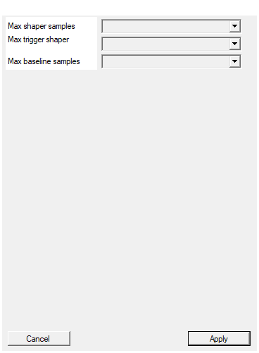
This parameters configure the number of samples used by the trapezoidal. It impact of the RAM memory usage in the FPGA
Maximum number of samples supported by the slow trapezoidal delay lines. Determines the maximum values for TRAP_K and TRAP_M parameters. Impacts FPGA RAM usage. Available values: 128, 256, 512, 1024, 2048, 4096, 8192, 16384, default 2048.Default: 2048
Options: 128 256 512 1024 2048 4096 8192 16384
This parameters configure the number of samples used by the trigger trapezoidal. It impact of the RAM memory usage in the FPGA
Maximum number of samples supported by the fast trapezoidal delay lines. Determines the maximum values for TRIG_K and TRIG_M parameters. Impacts FPGA RAM usage. Available values: 128, 256, 512, 1024, 2048, 4096, 8192, 16384, default 2048.Default: 2048
Options: 128 256 512 1024 2048 4096 8192 16384
Default: 2048
Options: 128 256 512 1024 2048 4096 8192 16384
Usage
Signal Flow Diagram
Processing Stages Detail
Stage 1: Fast Trapezoidal Trigger
The fast trapezoidal filter generates a trigger signal when a pulse is detected. It uses:
- Short peaking time (TRIG_K) for fast response
- Short flat-top (TRIG_M) for quick detection
- Derivative-based threshold comparison
The trigger is generated when the derivative of the trapezoidal output crosses the THRS threshold and then the signal reaches its peak (derivative crosses zero from positive to negative).
Advantages of derivative-based triggering:
- Does not require prior baseline calculation
- Immune to baseline shifts and DC offset
- Fast response time
Stage 2: Slow Trapezoidal Shaper
The slow trapezoidal filter provides high-resolution energy measurement:
- Longer peaking time (TRAP_K) for better noise filtering
- Appropriate flat-top (TRAP_M) for ballistic deficit compensation
- Integrated deconvolution (pole-zero cancellation) using DECONV_M
- Output gain adjustment with TRAP_GAIN
Trapezoidal Algorithm (Jordanov-Knoll):
$$ d^k[n] = x[n] - x[n-k] $$
$$ d^{k,l}[n] = d^k[n] - d^k[n-l] $$
$$ p[n] = p[n-1] + d^{k,l}[n] $$
$$ r[n] = p[n] + M \cdot d^{k,l}[n] $$
$$ s[n] = s[n-1] + r[n] $$
where:
- $k$ = peaking time (TRAP_K)
- $l$ = k + flat-top (TRAP_M)
- $M$ = deconvolution coefficient (DECONV_M)
Stage 3: Baseline Restorer
Calculates the DC baseline of the trapezoidal output using a moving average:
$$ \text{baseline}[n] = \frac{1}{2^{\text{BL_LEN}}} \sum_{i=0}^{2^{\text{BL_LEN}}-1} \text{trap}[n-i] $$
When a trigger occurs, the baseline calculation is held (frozen) for BL_INIB clock cycles to prevent pulse contamination.
Stage 4: Energy Sampler
Samples the baseline-subtracted trapezoidal signal at the optimal position:
$$ \text{energy} = \text{trap}[\text{trigger_time} + \text{SAMPLE_POS}] - \text{baseline} $$
The SAMPLE_POS parameter should be set to sample at the center of the flat-top region:
$$ \text{SAMPLE_POS} = \text{TRAP_K} + \frac{\text{TRAP_M} - \text{TRAP_K}}{2} $$
Calculating the Deconvolution Coefficient (DECONV_M)
The deconvolution coefficient removes the exponential tail from preamplifier signals:
$$ M = \frac{256}{e^{T_s / \tau} - 1} $$
where:
- $T_s$ is the sampling period (1 / clock_frequency)
- $\tau$ is the preamplifier decay time constant
- The factor 256 comes from the internal fixed-point scaling (8-bit shift)
Example calculation (Python):
python
import math
clock_freq = 125e6 # 125 MHz
tau = 50e-6 # 50 µs preamplifier decay time
Ts = 1.0 / clock_freq # 8 ns
M = int(256 / (math.exp(Ts / tau) - 1))
# Result: M = 1599744 (0x186A00)
For typical systems:
- f_clock = 125 MHz, τ = 50 µs: DECONV_M ≈ 0x186A00
- f_clock = 250 MHz, τ = 100 µs: DECONV_M ≈ 0x18A7E0
Input Delay Line
The input signal to the slow trapezoidal shaper is delayed by (TRIG_K + TRIG_M) samples. This ensures that the energy measurement window is properly aligned with the trigger timing:
Trigger fires at time T when pulse peak is detected
|
v
[----TRIG_K+TRIG_M delay----][----TRAP_K rise----][---flat-top---][----fall----]
^
|
Slow trap starts processing here
External Trigger Modes
The EXT_SEL input controls trigger source selection:
| EXT_SEL | Trigger Source |
|---|---|
| 0 | Internal trigger only |
| 1 | External trigger only (EXT_TRIG) |
| 2 | Internal AND External (coincidence) |
| 3 | Internal AND NOT External (anti-coincidence) |
Timing and Latency
- Total processing latency: 13 clock cycles from input to energy output
- Throughput: 1 sample per clock cycle (II=1)
- Trigger to energy delay: Configurable via SAMPLE_POS
Typical Applications
- Gamma-ray spectroscopy with HPGe detectors
- X-ray fluorescence (XRF) analysis
- Nuclear physics experiments
- Portable radiation detection systems
- Multi-detector coincidence systems