
Pulse Width
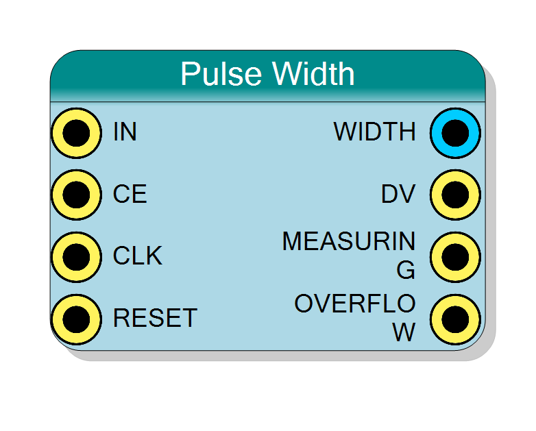
Measures the width of every pulse on a digital input, in clock cycles. Selectable polarity (high or low pulses), a one-clock DV strobe for each completed measurement, a MEASURING status and a saturation flag for pulses longer than the output range. Output width from 8 to 64 bits.
Introduction
This block measures how long each pulse on IN lasts, in clock cycles. A pulse is the time IN spends at its active level: ‘1’ with Pulse Polarity = High, ‘0’ with Pulse Polarity = Low.
When a pulse ends, WIDTH shows its duration and DV pulses for one clock. WIDTH then holds that value until the next pulse completes, so it can be read at any time.
$$ \mathrm{WIDTH} = \text{number of clocks IN was at the active level} $$
To convert to time: $t = \mathrm{WIDTH} / f_{\mathrm{clk}}$ (8 ns per count at 125 MHz).
Pin Description
Clock enable. When ‘0’ the block is frozen and the clocks are not counted.
Default: ‘1’ if left unconnected.
Clock. WIDTH is expressed in periods of this clock.
Default: global clock if left unconnected.
Reset, active high. Clears WIDTH, OVERFLOW and the measurement in progress.
Default: global reset if left unconnected.
Properties
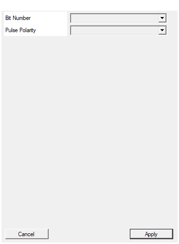
Set the number of bit of the WIDTH output (pulse width in clock cycles)
Width of WIDTH: 8, 16, 24, 32, 40, 48, 56, 64 bits. Sets the longest measurable pulse: 2^BitNumber - 1 clocks.Default: 32
Options: 8 16 24 32 40 48 56 64
High: measure how long IN stays at ‘1’. Low: measure how long IN stays at ‘0’.
- High: measure the time IN stays at ‘1’.
- Low: measure the time IN stays at ‘0’.
Default: High
Options: High Low
Functional description
Measurement
- IN passes a two-register synchroniser, so it can come from an asynchronous source.
- A pulse that lasts $W$ clocks at the pin gives WIDTH = W exactly. The shortest measurable pulse is 1 clock.
- MEASURING rises one clock after the leading edge at the pin and falls with DV.
- DV and the new WIDTH appear one clock after the trailing edge at the pin. DV lasts one clock.
- Between pulses WIDTH and OVERFLOW hold the last result.
Pulses with no leading edge
A pulse that is already active when RESET is released (or at power-up) is ignored: its start is unknown, so its width would be wrong. The first measurement is the first pulse whose leading edge is seen. A RESET in the middle of a pulse drops that pulse for the same reason.
Saturation
A pulse longer than $2^N-1$ clocks does not wrap: WIDTH saturates at $2^N-1$ and OVERFLOW is set together with that DV. Read it as “at least $2^N-1$”. OVERFLOW refers to the WIDTH currently shown and is cleared by the next normal measurement.
CE and RESET
- CE=‘0’ freezes the block (synchroniser and counter); those clocks are not counted and DV reads ‘0’.
- RESET clears WIDTH, OVERFLOW and any measurement in progress.
Timing diagram
A 5-clock high pulse (Pulse Polarity = High):
The Test Timing window (right click on the block) shows a simulated demonstration: an ignored pulse in progress at start, pulses of 5 and 1 clocks, the held WIDTH, and an 8-bit saturation with OVERFLOW.
Choosing Bit Number
| Bit Number | Max WIDTH | @ 125 MHz | @ 250 MHz |
|---|---|---|---|
| 8 | 255 | 2.04 µs | 1.02 µs |
| 16 | 65 535 | 524 µs | 262 µs |
| 24 | 16 777 215 | 134 ms | 67 ms |
| 32 | 4 294 967 295 | 34.4 s | 17.2 s |
Typical use cases
- Time-over-threshold (ToT) of a discriminator output.
- Gate / veto / busy duration monitoring.
- Pulse width of trigger or handshake signals.
- Combined with a Freq Meter to obtain the duty cycle.
Resources & Timing
-
Latency: WIDTH/DV one clock after the trailing edge at the pin
-
Throughput: one measurement per pulse; consecutive pulses of any length, down to 1 clock high + 1 clock low
Two N-bit registers (counter and result) and a few flip-flops. No DSP, no BRAM.