Pins, Variables & Registers Workflow
How to work with pins as first-class objects in the diagram editor: select single pins, ranges or rectangles of pins, give every block a persistent Common Name, and turn pins or nets into variables, ports, registers, register files and constants with automatic wiring.
Introduction
The diagram editor treats pins as selectable objects. Once one or more pins are selected, the right-click menu offers a set of one-click actions that create variables, ports, registers or constants already wired to the pins, removing most of the manual plumbing from repetitive designs.
Block Common Name
Every block owns a persistent Common name, used as prefix whenever the editor
generates named objects from its pins (variables COMMON_PIN, registers COMMON_PIN, …).
- A default is assigned automatically when the block is placed: the component name plus a
progressive number when more blocks of the same type live on the page (
Trigger,Trigger_2, …). - It can be edited directly in the right-click menu of the block, in the Common name text field under the Node Menu section.
- It is saved with the project and preserved across property edits and IP upgrades.
- Names are validated with the standard rules (letters, digits, underscore, no leading digit, no HDL reserved words).
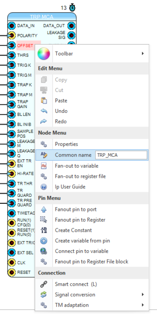
Figure 1: the Common name field in the block contextual menu
Selecting Pins
| Action | Effect |
|---|---|
| Click on a pin row | Selects that pin (highlighted in red) |
| Ctrl + click | Adds / removes a pin from the selection (works across blocks) |
| Shift + click | First click sets the range start, second click selects the whole vertical range; a third Shift+click starts a new range |
| Drag from inside a block body | Rubber-band selection: every pin whose bullet falls inside the rectangle is selected (Ctrl adds to the selection) |
| Click on canvas / caption / other block | Clears the pin selection |
Notes:
- A new net can only be started by dragging from the pin bullet at the block edge; dragging from the middle of the block always selects pins.
- Rubber-band selection started outside a block keeps the normal behaviour (selects blocks and nets).
- Blocks are selected by clicking their caption; a selected block can be moved by dragging its body.
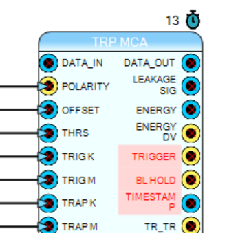
Figure 2: a multi-pin selection (red pins) made with Ctrl+click
Pin Menu Actions
With one or more pins selected, right-click a pin to open the contextual menu. The Pin Menu section offers:
Create variable from pin
Creates one variable per selected pin, named <Common name>_<pin>. A preview window lists
every variable that will be created; the common name is editable in place. On confirm each
variable is added to the page variable list and its VAR block is placed in front of the
pin and wired: outputs get a Variable Read on the right, inputs a Variable Write on
the left.
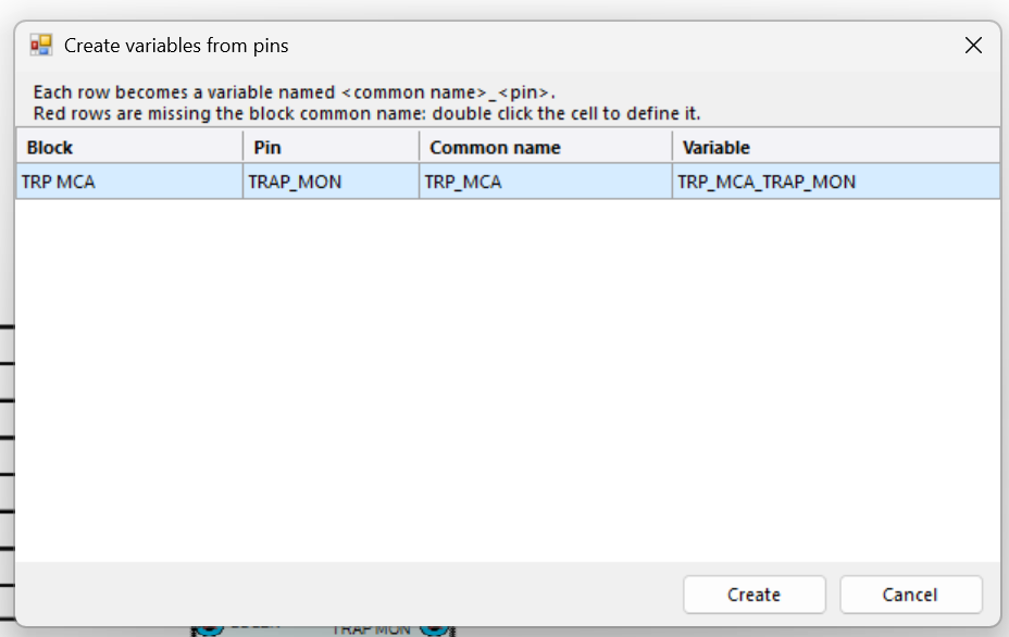
Figure 3: the variables preview window
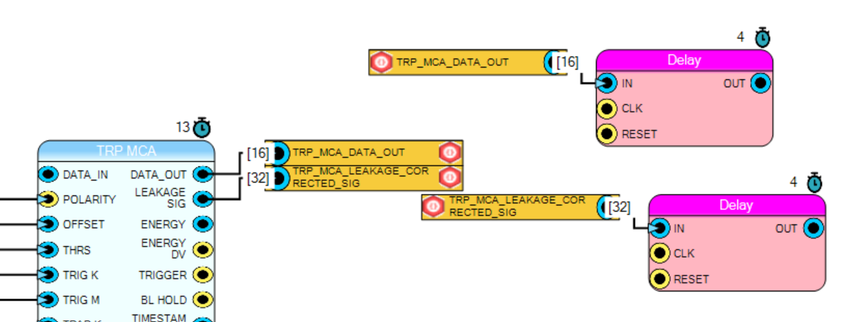
Figure 4: the result — each output pin gets its named variable (Variable Read) wired in front of it, and the same variables can then be read anywhere on the page through Variable Write blocks
Connect pin to variable
- Single pin: opens the quick variable picker (same list as the quick menu
P → Variables); the chosen variable block is placed in front of the pin and wired. - Multiple pins: opens the mapping window — variables with search box on the left, one row per pin on the right. Connect by typing (autocomplete), dragging variables onto the rows (multi-selection supported), or with the center arrows. Rows can be reordered by dragging their ⠿ handle or with the up/down buttons. Type / size / TM compatibility is verified live (✔ / ✘ icons) and after each association the focus moves to the next row.
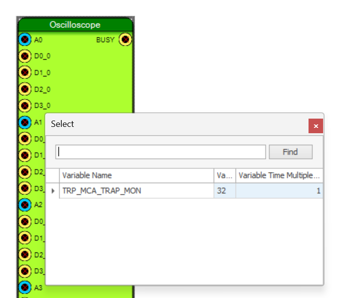
Figure 5: the multi-pin variable mapping window
Fanout pin to port / to Register / Create Constant
The classic single-pin actions now support the multi selection and wire what they create:
- Fanout pin to port: one SCHEMATIC ENTRY per pin, named after the pin, connected.
- Fanout pin to Register: one register
<Common>_<pin>per pin, created in the page register file, REG block placed in front of the pin and connected (Register Write for outputs, Register Read for inputs). - Create Constant: one constant per selected input pin; the value is asked once per signal family, the bit size follows each pin, and every constant is wired.
Fanout pin to Register File block
Builds a Register File component definition straight from the selected pins: design outputs become readable registers, inputs become writable ones. The standard customization dialog opens with the register list already filled (editable); on confirm the block is placed next to the pins and every pin is wired to its register.
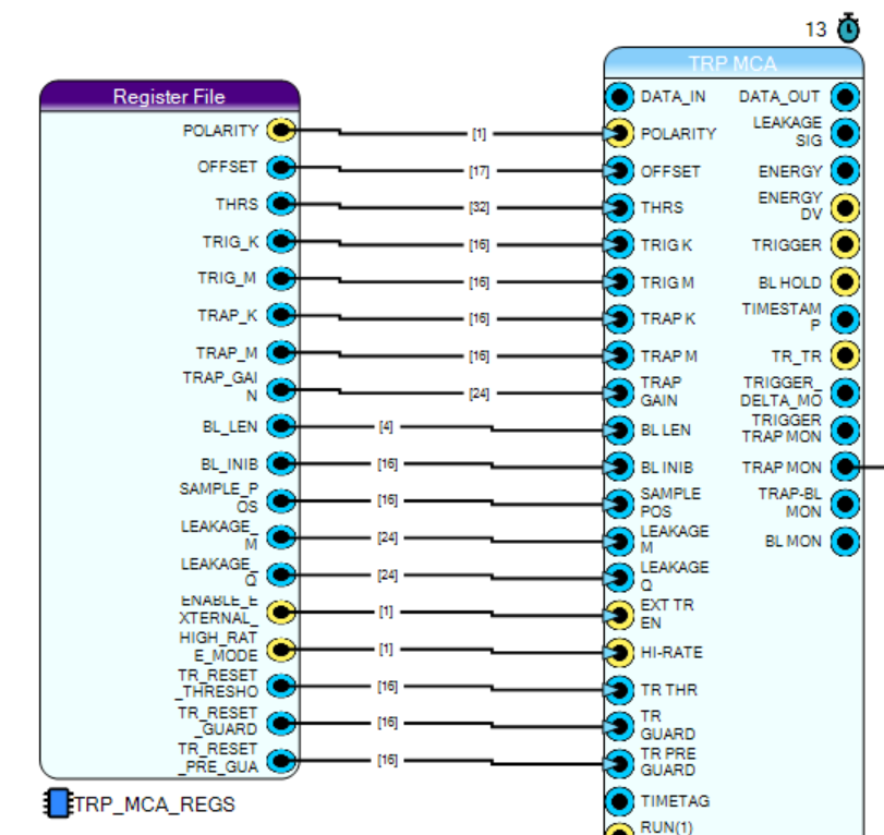
Figure 6: register file generated from a pin selection
Node Menu Actions
Right-clicking a block offers two block-level fan-outs (no dialog: the Common name property drives the naming):
- Fan-out to variable: one variable
<Common>_<pin>per pin of the block, VAR blocks placed and wired. Inputs already driven by a net are skipped. - Fan-out to register file: same, but with registers in the page register file.
Replace Net with Variable
Select one or more nets (Ctrl+click to multi-select), right-click and choose Replace net
with variable. A preview window lists the variables that will be created
(<source Common name>_<source pin>); rows whose source block has no Common name yet are
shown in red and block the operation — selecting such a row zooms the diagram (~50%)
on the source block with the net highlighted, and the Common name can be typed directly in
the grid. On confirm the source pin gets a wired Variable Read, every destination pin a
wired Variable Write, and the original nets are removed.
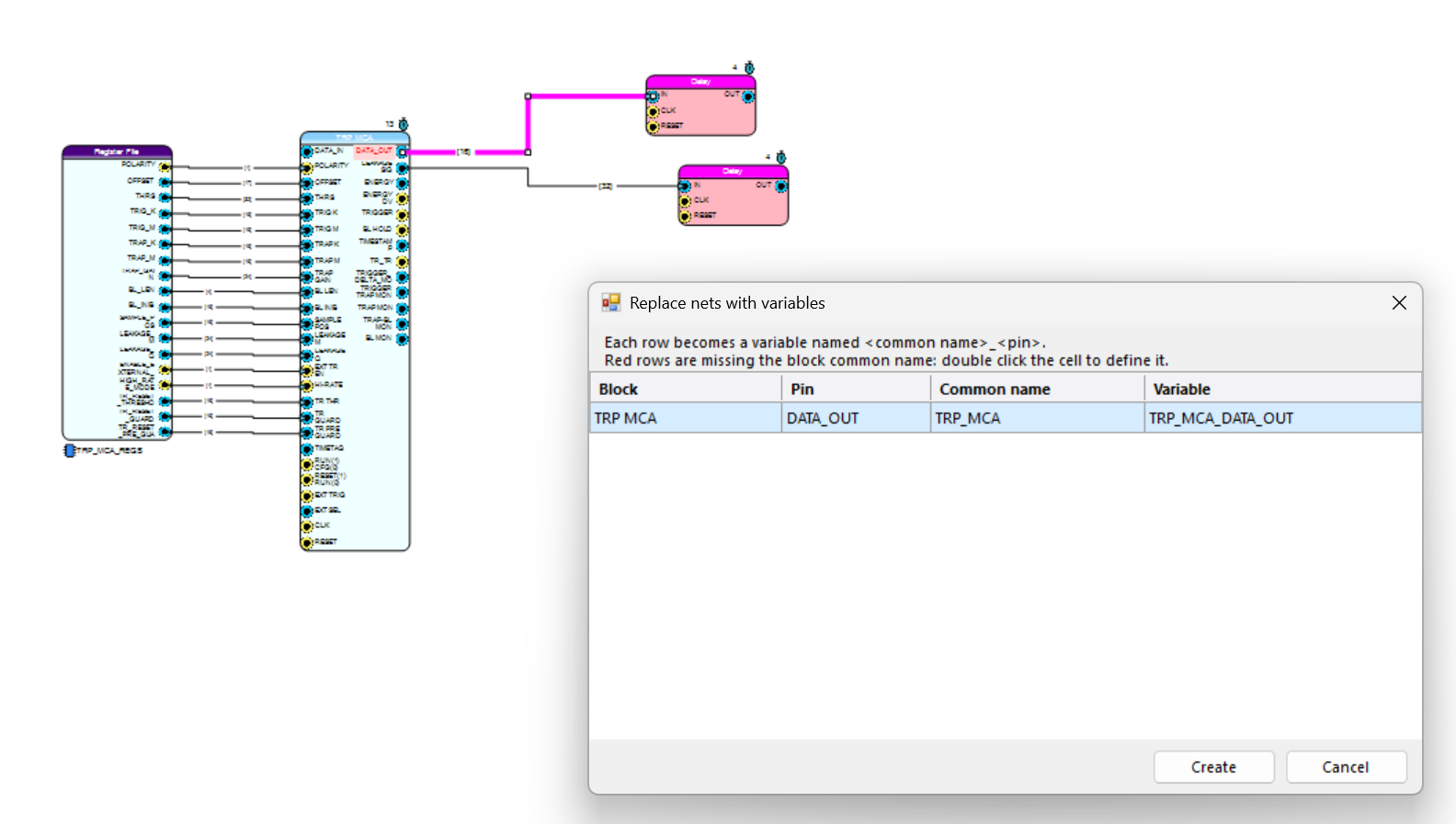
Figure 7: net conversion preview with a missing common name (red row)
Connect to Block (from the Variables window)
In the Variables window, select one or more variables, right-click the list and choose Connect to block…: the cursor becomes a yellow picker; click the target block and the variable mapping window opens on all its pins with the chosen variables preselected.