
Serial Bus - Status Packet RX
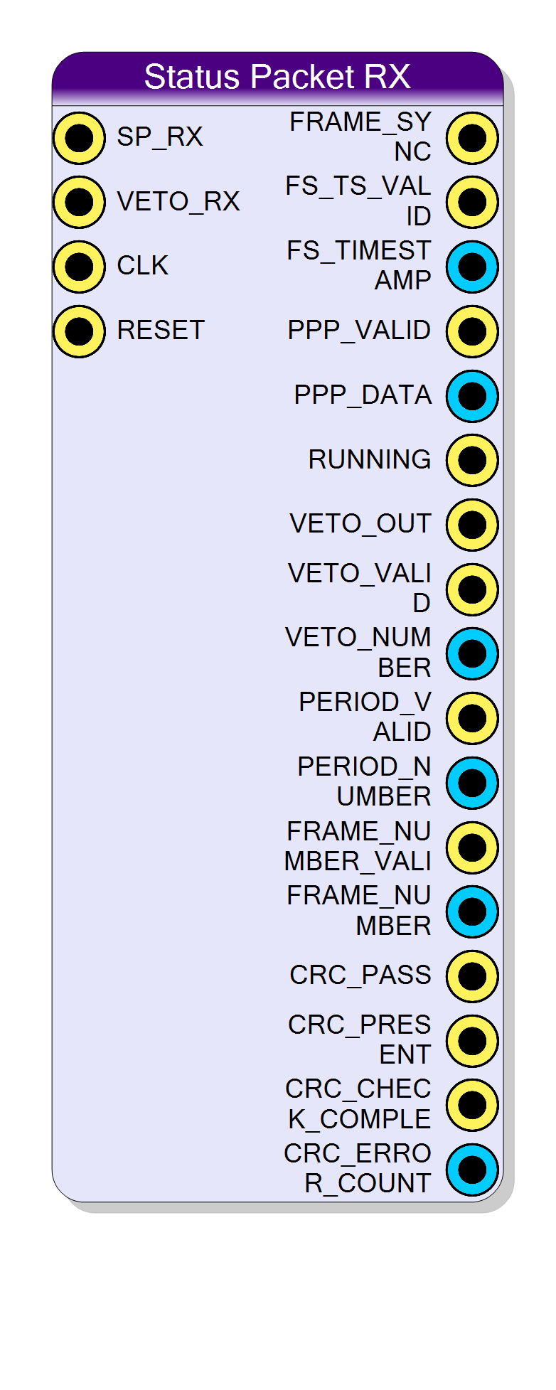
Receiver for the 16-byte time/period/PPP/run/frame-number status packet and the paired 2-byte veto packet broadcast over two asynchronous serial lines. Decodes the packet on the fly and exposes every field in parallel together with a CRC32 verification result.
Introduction
The Status Packet RX block receives a fixed-format timing broadcast over two unidirectional UART-like lines and presents every decoded field as parallel buses for the rest of the design.
Two serial inputs carry the broadcast:
- SP_RX - status packet line (timestamp + period + PPP + running + frame number)
- VETO_RX - companion veto line (2-byte veto word per veto event)
Key features:
- Self-recovering frame-sync detection on both lines
- 16-byte status packet decoder + 2-byte veto decoder
- 64-bit timestamp, 16-bit period number, 32-bit frame number
- 8-bit PPP word and 1-bit running flag
- Optional CRC32 verification of the status packet payload
- Internal UART divider computed from the configured clock and baud rate
Pin Description
CLK_FREQ_HZ / BaudRate ratio of 16 or more is recommended).
Default: Acquisition clock.
FS_TIMESTAMP has been refreshed
(after byte 7 of the packet).
PPP_DATA has been refreshed
(after byte 10 of the packet).
FRAME_NUMBER.
Stays stable until the next packet rewrites it.
VETO_NUMBER has been refreshed
(after the 2nd veto byte).
PERIOD_NUMBER has been refreshed
(after byte 9 of the packet).
FRAME_NUMBER has been refreshed
(after byte 15 of the packet).
CRC verification result. Latched when CRC_VALID pulses.
- HIGH: received CRC32 matches the computed one (or CRC is disabled).
- LOW: CRC mismatch or aborted packet.
CRC_CHECK_COMPLETE and then holds until the next packet completes.
Zero after reset.
CRC_PASS and
CRC_PRESENT; it is the only qualifier those two levels have.
CRC_CHECK_COMPLETE, on a CRC mismatch and on a packet
whose CRC trailer was interrupted by an early frame-sync. A packet with a
passing CRC, or with no CRC trailer at all, does not increment it. There
is no clear-on-read: the only way back to zero is RESET.
Properties
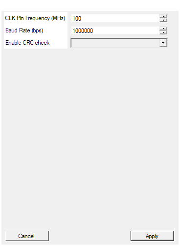
Set the input clock frequency in MHz (used to compute the UART divider together with the Baud Rate)
Frequency of the CLK input in MHz. Combined with the baud rate to compute the internal UART divider.
Typical values:
- 50 MHz: V2495 default
- 80 MHz: DT5550 default
- 100-200 MHz: High-speed designs
Default: 100
Range: 1 – 500
Set the status packet serial baud rate in bits per second (used to compute the UART divider)
Status packet line speed in bits per second. Must match the transmitter setting on both SP_RX and VETO_RX.
Common values used with this protocol:
- 9600: legacy / long cable runs
- 115200 - 921600: typical lab setups
- 1000000: default high-speed setting
The synthesized UART divider is computed as
floor(CLK_FREQ_HZ / BaudRate); mismatches of more than a few percent
between transmitter and receiver may cause byte-level errors.
Default: 1000000
Range: 300 – 10000000
Enable the CRC32 check at the end of each status packet
Enables CRC32 verification of the 16-byte status payload.
- Disabled: the receiver stops decoding after the frame-number byte;
CRC_PASSis permanently asserted at end-of-packet and the 4 CRC bytes (if sent) are ignored. - Enabled: the receiver expects the 4 CRC32 bytes (Ethernet
polynomial
0xEDB88320) right after the frame-number;CRC_PASSreflects the comparison andCRC_ERRORpulses on mismatch.
The setting must match the transmitter configuration; if they disagree
either spurious CRC_ERROR or a stuck decoder may result.
Default: Disabled
Options: Disabled Enabled
Functional description
The block listens to two asynchronous serial lines (SP_RX and VETO_RX) that share the same baud rate. Each line is processed independently:
- A frame-sync generator watches the line for a long start-low condition (longer than a single UART start bit) and emits a clean 1-clock FRAME_SYNC / VETO_OUT strobe once the pulse has been validated.
- A UART receiver shifts each subsequent 8-bit byte into the decoder.
- A packet decoder re-assembles the bytes into the parallel fields below
and pulses the corresponding
*_VALIDstrobe when the field is updated.
Status packet layout (SP_RX line)
After the frame-sync, the transmitter sends 16 bytes; with CRC enabled 4 additional CRC32 bytes follow. Byte order:
| Byte | Field | Output bus |
|---|---|---|
| 0..7 | 64-bit timestamp (MSB first) | FS_TIMESTAMP[63:0] |
| 8..9 | Period number (MSB first) | PERIOD_NUMBER[15:0] |
| 10 | PPP data | PPP_DATA[7:0] |
| 11 | Running flag (bit 0) | RUNNING |
| 12..15 | Frame number (MSB first) | FRAME_NUMBER[31:0] |
| 16..19 | CRC32 (LSB first, optional) | - |
The corresponding *_VALID strobe pulses for one clock cycle as soon as the
last byte of the field is written, so downstream logic can latch each field
independently.
Veto packet layout (VETO_RX line)
When a veto pulse is detected on VETO_RX, two bytes follow:
| Byte | Field | Output bus |
|---|---|---|
| 0 | veto high byte | VETO_NUMBER[15:8] |
| 1 | veto low byte | VETO_NUMBER[7:0] |
VETO_VALID pulses one clock cycle after the second byte is captured. The
veto word is automatically cleared at the next FRAME_SYNC.
CRC32 verification
When the Enable CRC check property is enabled, the decoder accumulates a
CRC32 (Ethernet polynomial 0xEDB88320) over the 16 payload bytes and
compares it against the 4 trailing CRC bytes. The result is exposed on
three flags:
- CRC_PASS - high if the received CRC matches the computed value.
- CRC_ERROR - pulses high for one cycle when the CRC fails.
- CRC_VALID - pulses high for one cycle when CRC_PASS / CRC_ERROR / CRC_ABORT are updated; sample the others on this edge.
- CRC_ABORT - pulses high when a new FRAME_SYNC arrives before the CRC bytes were fully received (truncated packet).
With CRC disabled, CRC_PASS and CRC_VALID still pulse at the end of every packet but the comparison is skipped (CRC_PASS is always ‘1’).
UART clock divider
The internal divider that converts the system clock into the UART baud reference is computed at synthesis time as:
$$ DIV = \left\lfloor \frac{f_{CLK}}{BaudRate} \right\rfloor $$
For example, 100 MHz / 1 Mbps → DIV = 100, 50 MHz / 9600 bps → DIV = 5208.
Timing notes
- FRAME_SYNC is asserted as soon as the long start-low pulse on SP_RX has been validated; it does not wait for the payload bytes.
- VETO_OUT mirrors the frame-sync logic on the veto line, so it is a timestamp of the veto pulse independent of the 2-byte decoder.
*_VALIDstrobes are 1-clock pulses synchronous to CLK.FS_TIMESTAMP,PERIOD_NUMBER,PPP_DATA,FRAME_NUMBER,VETO_NUMBERandRUNNINGstay stable between two valid updates.
Reset Behavior
The RESET input is active high (driven from the project Global Reset by default):
- All decoders return to the frame-sync wait state.
- All
*_VALIDstrobes are forced low. - Stored values (timestamp, frame number, …) are cleared.