
Demultiplexer
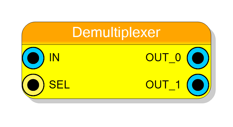
1-to-N demultiplexer that routes a single input to one of multiple outputs based on a binary select signal. Supports 2 to 16384 outputs with configurable word size. Pure combinational logic with zero latency.
Introduction
This block implements a standard demultiplexer (DEMUX) that routes a single input to one of multiple outputs. The routing is controlled by a binary select signal:
$$ \mathrm{OUT}_i = \begin{cases} \mathrm{IN} & \text{if } i = \mathrm{SEL} \ 0 & \text{otherwise} \end{cases} $$
Only the selected output receives the input data; all other outputs are zero.
Pin Description
Properties
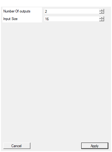
Set the number of outputs
Number of output ports. Range: 2-16384. Determines how many OUT_x ports are created and the width of the SEL signal.Default: 2
Range: 2 – 16384
Set the size in bit of inputs
Number of bits for the input and each output. Range: 1-16384 bits. All data ports must have the same width.Default: 16
Range: 1 – 16384
Functional description
The Demultiplexer component implements a 1-to-N data distributor. It routes the input signal IN to one of N output ports (OUT_0 to OUT_(N-1)) based on the select signal, while all non-selected outputs are driven to zero.
Distribution Operation
For each output $i$: $$ \mathrm{OUT}_i = \begin{cases} \mathrm{IN} & \text{if } i = \mathrm{SEL} \ \vec{0} & \text{otherwise} \end{cases} $$
The select signal width is automatically calculated as: $$ \text{SEL width} = \lceil \log_2(N) \rceil \text{ bits} $$
Example
For a 1-to-4 DEMUX (4 outputs):
- SEL width = 2 bits
- SEL = 00 (0) → OUT_0 = IN, OUT_1 = 0, OUT_2 = 0, OUT_3 = 0
- SEL = 01 (1) → OUT_0 = 0, OUT_1 = IN, OUT_2 = 0, OUT_3 = 0
- SEL = 10 (2) → OUT_0 = 0, OUT_1 = 0, OUT_2 = IN, OUT_3 = 0
- SEL = 11 (3) → OUT_0 = 0, OUT_1 = 0, OUT_2 = 0, OUT_3 = IN
Out of Range Selection
If SEL exceeds the number of outputs, all outputs are driven to zero.
Implementation
The demultiplexer is implemented using conditional assignment in VHDL. Each output has a separate conditional check against the SEL value, resulting in efficient hardware (typically implemented as LUT-based logic in FPGAs).
Latency and Timing
| Property | Latency (clock cycles) |
|---|---|
| Demultiplexer | 0 |
The component has zero latency (purely combinational).
Typical use cases
- Data distribution and routing
- Address-based signal routing
- Building memory address decoders
- Distributing control signals
- Time-division demultiplexing