On this page

LED Vector
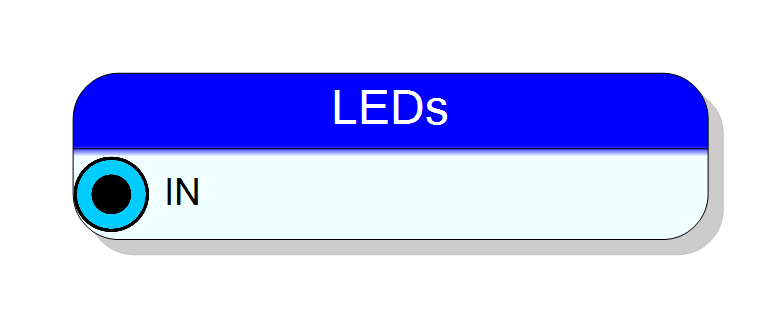
8-bit LED output interface for V2495 front panel. Displays an 8-bit binary value on the front panel LEDs.
Introduction
The LED Vector block controls the 8 front panel LEDs on the V2495 board. An 8-bit input value directly controls which LEDs are illuminated.
This is useful for debugging, status indication, and visual feedback.
Pin Description
IN
Input
8 bit
BIT VECTOR
IN (LED[0...7])
Input
8 bit
8-bit input vector controlling the LEDs.
| Bit | LED |
|---|---|
| IN[0] | LED 0 |
| IN[1] | LED 1 |
| IN[2] | LED 2 |
| IN[3] | LED 3 |
| IN[4] | LED 4 |
| IN[5] | LED 5 |
| IN[6] | LED 6 |
| IN[7] | LED 7 |
Each bit = 1 turns ON the corresponding LED.
Properties
(none)
(none)
The LED Vector block has no configurable properties.
LED states are controlled directly by the input vector.
Usage
LED Mapping
The 8-bit input vector directly maps to the 8 front panel LEDs:
┌──────────────────────────────────────────────────────────────────┐
│ LED Vector Mapping │
│ │
│ Input: [7][6][5][4][3][2][1][0] │
│ │ │ │ │ │ │ │ │ │
│ ▼ ▼ ▼ ▼ ▼ ▼ ▼ ▼ │
│ LEDs: [7][6][5][4][3][2][1][0] │
│ │
│ Bit = 1: LED ON │
│ Bit = 0: LED OFF │
└──────────────────────────────────────────────────────────────────┘
Example Values
| Input Value (Binary) | Input Value (Hex) | LEDs ON |
|---|---|---|
| 00000001 | 0x01 | LED 0 |
| 00000011 | 0x03 | LED 0, LED 1 |
| 10101010 | 0xAA | LED 1, 3, 5, 7 |
| 11111111 | 0xFF | All LEDs |
| 00000000 | 0x00 | None |
Typical Usage
Use the LED Vector for:
- Debugging: Display internal state values
- Status indication: Show operational modes or error codes
- Binary counters: Visualize counting sequences
- Trigger activity: Display which trigger channels are active
Example: Binary Counter Display
Resources & Timing
-
Latency: Minimal (direct connection to LED drivers)
-
Throughput: Updates at FPGA clock rate
- 8 front panel LEDs on V2495
- Direct bit-to-LED mapping
- No configuration required
Supported Boards
- V2495