TRP MCA
A fully–pipelined trapezoidal-shaper IP core derived from the Jordanov algorithm and optimised for detectors equipped with transistor-reset pre-amplifiers. The core computes an amplitude-invariant energy estimate, subtracts continuous leakage current, detects automatic pre-amplifier resets and outputs time-tagged energy words at sustained single-sample throughput. Deconvolution of exponential decay is deliberately omitted because the input step waveform does not exhibit a decay constant.
Introduction
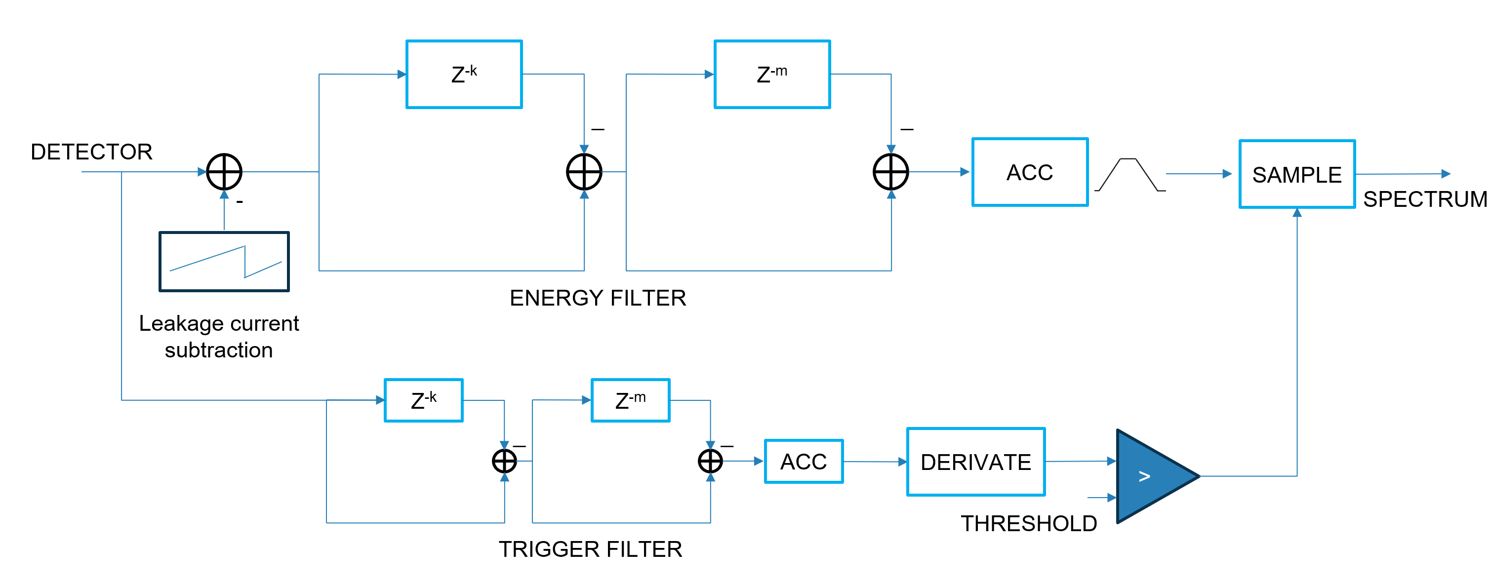
The TRP MCA block implements a pair of trapezoidal filters:
- a fast trigger filter, generating a low-latency
TRIGGER_OUT; - a slow energy filter delivering the shaped amplitude (
DATA_OUT) and a time-aligned energy sample (ENERGY).
Unlike classical spectroscopy chains, the pre-amplifier used here is periodically reset, producing a staircase at the ADC input.
Consequently:
• the exponential deconvolution stage normally required for RC pre-amps is not present;
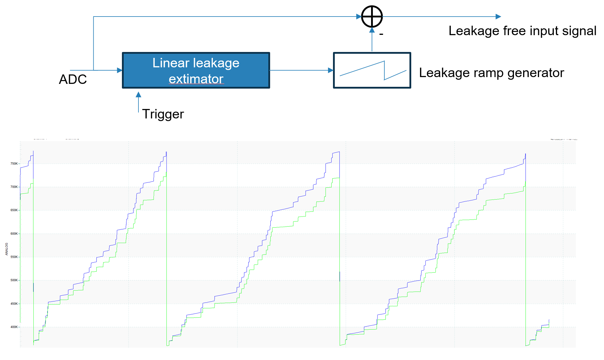
• a leakage-current estimator / subtractor keeps the staircase flat between resets;
• an internal reset detector inhibits filtering during the large perturbation introduced by each reset.
The overall data path is fully streaming (II = 1) and can be used in either time-multiplexed or parallel designs. A single clock domain must be provided
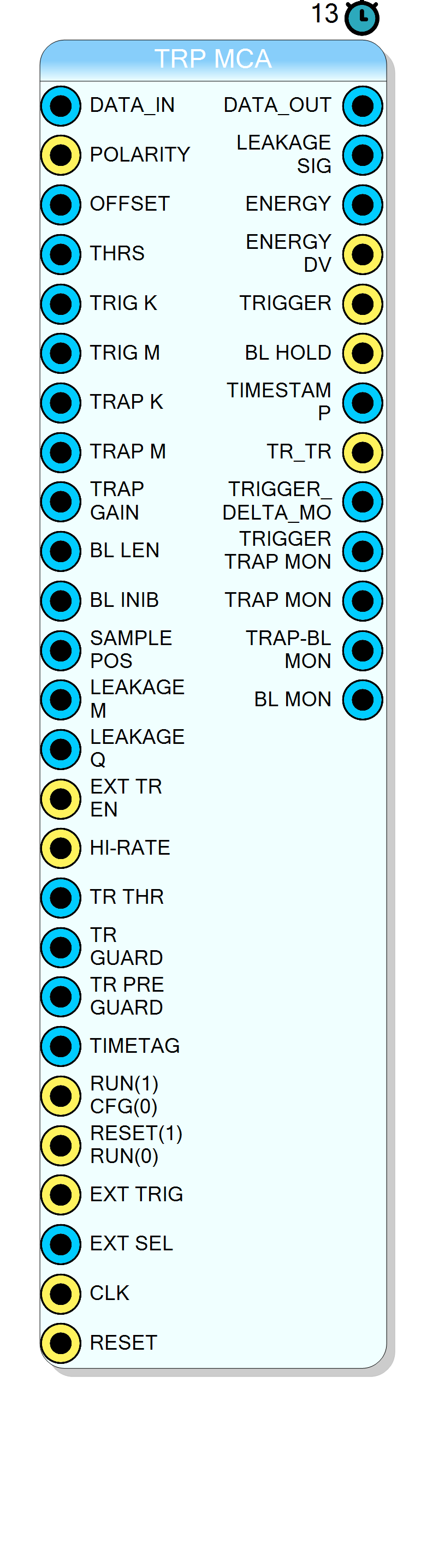
Pin Description
1 = pulses are positive; 0 = pulses are negative. Selects internal inversion path.
BL_HOLD).
1 = use pin TR_RESET; 0 = use automatic reset detector.
TRIGGER_OUT and re-transmitted with energy word.
1 = run mode; 0 = configuration/idle. All accumulators frozen while 0.
TRAP_MON).
ENERGY_STROBE=1.
Properties
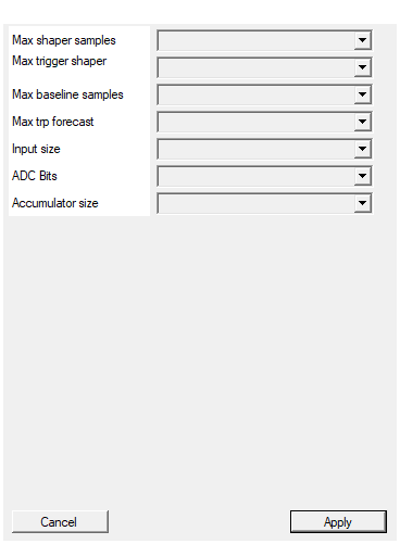
This parameters configure the maximum number of samples used by the trapezoidal. It impact of the RAM memory usage in the FPGA
Maximum depth of the energy delay lines (samples). Larger values allow longer peaking times but consume more block-RAM.Default: 2048
Options: 128 256 512 1024 2048 4096 8192 16384
This parameters configure the maximum number of samples used by the trigger trapezoidal. It impact of the RAM memory usage in the FPGA
Maximum depth of the trigger delay lines (samples). Must be ≥TRIG_K + TRIG_M.
Default: 128
Options: 16 32 64 128 256 512
BL_LEN.
Default: 2048
Options: 128 256 512 1024 2048 4096 8192 16384
Default: 128
Options: 32 64 128 256 512 1024 2048
DATA_IN and internal arithmetic datapath. Changing this parameter resynthesises the core.
Default: 24
Options: 12 14 16 20 24 28 32 64
ADC_BITS_N in over-range conditions.
Default: 20
Options: 12 14 16 18 20 22 24 26 28 30 32
Default: 64
Options: 32 48 64 80 96 128
Theory of operation
A Jordanov trapezoid is obtained by the difference of two rectangular moving sums:
$$ T[n] = \sum_{i=0}^{k-1}x[n-i] - \sum_{i=k+m}^{2k+m-1}x[n-i] $$
where
k = flat-top/peaking length,
m = gap between the two sums.
The digital implementation used here is split in three sections:
Trigger filter
Implemented with parameters TRIG_K, TRIG_M, THRS.
The instantaneous delta
$$
\Delta[n] = \sum_{i=0}^{k-1}x[n-i] - \sum_{i=k+m}^{2k+m-1}x[n-i]
$$
is compared with THRS. Once the threshold is crossed, a trigger candidate is opened for (2·k) samples and validated if the delta subsequently changes sign (bipolar detection).
Guard windows (TR_INHIBIT_TRIGGER) protect the chain after each reset.
1.2 Energy filter
Using TRAP_K, TRAP_M, TRAP_GAIN the shaped signal is
$$
S[n] = \frac{G}{2^{16}},
\Bigl[\sum_{i=0}^{k-1}x[n-i]-\sum_{i=k+m}^{2k+m-1}x[n-i]\Bigr]
$$
An accumulator of LARGE_ACC_BITS guarantees distortion-free long integrations.
Leakage current cancellation
The ADC sample $x[n]$ is corrected as
$$
x_\ell[n] = x[n] - \frac{L[n]}{2^{20}}
$$
with
$$ L[n] = \begin{cases} L[n-1] + \text{LEAKAGEM} & \text{while no reset} \ \text{LEAKAGEQ} & \text{immediately after reset.} \end{cases} $$
Baseline restorer
A moving average of depth $2^{\text{BLLEN}}$ tracks the residual baseline while ignoring a configurable inhibition window BL_INIB after each validated trigger.
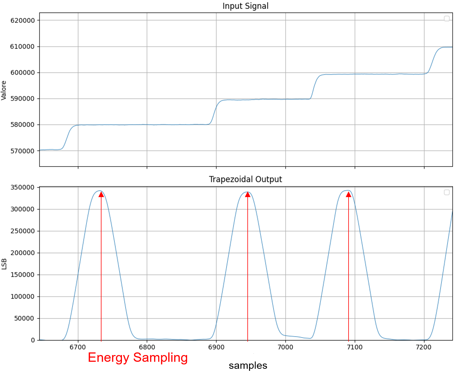
Energy sampler
After a programmable delay SAMPLE_POS, the value
$E = S[n]-\text{Baseline}$
is captured and flagged on ENERGY_STROBE. The 64-bit TIMESTAMP present at the trigger leading edge is re-broadcast to keep event/energy correlation.
Reset detection
If ENABLE_EXTERNAL_RESET = 0 the ADC stream is monitored; whenever
$$
x[n] < \text{TrResetThreshold}
$$
a reset is declared and the processing chain is inhibited for TR_RESET_GUARD samples. Pre-guard delay TR_RESET_PRE_GUARD ensures that the large glitch never pollutes the trigger pipeline.
Timing
For continuous streaming:
-
Trigger latency
$$L_{trig} \approx 2k+m+6\text{ clk}$$
(k and m refer toTRIG_K,TRIG_M). -
Shaper output latency
$$L_{shaper} \approx 2k+m+6\text{ clk}$$
(k and m refer toTRAP_K,TRAP_M). -
Energy latency
$$L_E = L_{shaper} + \text{SamplePos}$$
All internal pipelines are one-sample-per-clock (II = 1).
FPGA resources
Memory usage grows linearly with the maximum depths selected in the properties panel
(PRE_LEN, TRIGGER_PRE_LEN, BASELINE_PRE_LEN, TR_RESET_DELAY).
The provided default (2048 samples) fits comfortably in one BRAM18 per delay line on a typical Series-7 FPGA.
Typical use-case
A transistor-reset HPGe detector is digitised by the ADC; the TRP MCA produces a dead-time-free energy spectrum while suppressing leakage drift and reset artefacts.