
IIR Elliptic - II Order
Second-order Elliptic (Cauer) IIR filter with the steepest roll-off. Features both passband and stopband ripple for maximum frequency selectivity.
Introduction
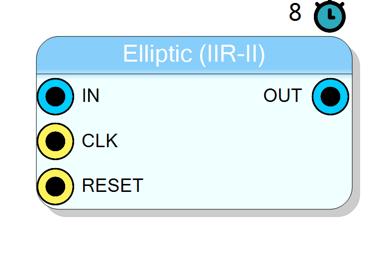
The IIR Elliptic - II Order block implements a second-order Elliptic (also known as Cauer) IIR filter operating in real time on FPGA. The component includes automatic filter coefficient calculation based on filter type (low/high pass), cutoff frequency, passband ripple, and stopband attenuation.
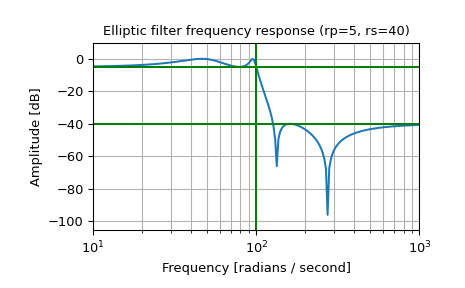
Elliptic filters have the steepest roll-off of all standard filter types for a given order, achieved by allowing ripple in both passband and stopband.
Pin Description
Properties
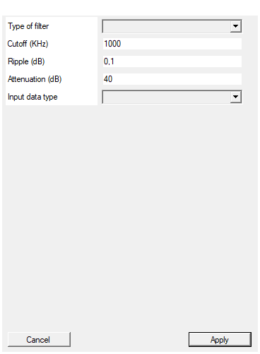
Select between low pass and high pass filter
Filter type selection. Available values: Low Pass, High Pass, default Low Pass.Default: Low Pass
Options: Low Pass High Pass
Set the filter pole/zero position according to the selected bandwidth in KHz
Cutoff frequency in kHz. Must be less than half the sampling frequency (Nyquist limit).Default: 1000
The maximum ripple allowed below unity gain in the passband. Specified in decibels, as a positive number.
Passband ripple in dB. Maximum allowed variation in the passband. Typical values: 0.5 to 3 dB.Default: 0.1
The minimum attenuation required in the stop band. Specified in decibels, as a positive number.
Stopband attenuation in dB. Minimum attenuation guaranteed in the stopband. Typical values: 20 to 60 dB.Default: 40
Select input data type
Input data format selection. Available values: Unsigned 16 bit, Signed 17 bit, default Unsigned 16 bit.Default: UINT16
Options: UINT16 INT17
Usage
Elliptic Filter Characteristics
Elliptic filters provide the most efficient frequency selectivity at the cost of ripple in both bands:
- Steepest Roll-off: Maximum transition steepness for given filter order
- Passband Ripple: Controlled ripple in passband (specified in dB)
- Stopband Ripple: Controlled attenuation in stopband (specified in dB)
- Equiripple Behavior: Optimal distribution of approximation error
Comparison with Other Filters
| Filter Type | Passband | Stopband | Roll-off |
|---|---|---|---|
| Butterworth | Flat | Flat | Moderate |
| Chebyshev 1 | Ripple | Flat | Steep |
| Chebyshev 2 | Flat | Ripple | Steep |
| Elliptic | Ripple | Ripple | Steepest |
Scattered Lookahead Implementation
To enable real-time FPGA operation at full clock rate, the filter uses the Scattered Lookahead technique:
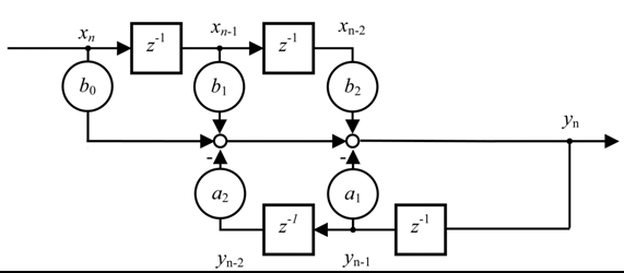
The standard IIR equation:
$$ y[n] = b_0 x[n] + b_1 x[n-1] + b_2 x[n-2] - a_1 y[n-1] - a_2 y[n-2] $$
Is transformed using scattered lookahead to:
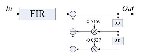
$$ y[j] = \sum_{k=0}^{6} b’_k x[j-k] - a’_3 y[j-3] - a’_6 y[j-6] $$
Reference: A universal look-ahead algorithm for pipelining IIR filters
Coefficient Calculation
SciCompiler automatically calculates the filter coefficients. The following Python code provides a reference implementation:
python
import numpy as np
from scipy import signal
def scattered_lookahead_transform(a):
A = np.array([[a[0], 0, 0, 0, 0, ],
[a[1], a[0], 0, 0, 0, ],
[a[2], a[1], a[0], 0, 0, ],
[0, 0, a[2], a[1], a[0], ],
[0, 0, 0, a[2], a[1], ]])
A_inv = np.linalg.inv(A)
D = A_inv * [1, 0, 0, 0, 0]
D1 = D[:,0]
D = D[:,0].reshape(-1, 1)
R = np.array([[ 0, a[2], a[1], a[0], 0, ],
[0, 0, 0, 0, a[2]]])
Qw = np.dot(R, D)
an = [1, Qw[0][0], Qw[1][0]]
bn = D1
return bn, an
N = 2 # Order of the filter
fs = 250*1e6 # Sampling frequency
fc = 5*1e6 # Corner frequency
rp = 1 # Passband ripple in dB
rs = 40 # Stopband attenuation in dB
Wn = fc/(fs/2)
b_z, a_z = signal.ellip(N, rp, rs, Wn, btype='low')
print("original", b_z, a_z)
bn, an = scattered_lookahead_transform(a_z)
bq = np.convolve(bn, b_z)
aq = an
print("scattered", bq, aq)
Typical Applications
- Applications requiring maximum frequency selectivity
- Narrow transition band requirements
- Channel separation filters
- Where ripple in both bands is acceptable
Resources & Timing
- Latency: 8 clock cycles