
Logic OR [TM]
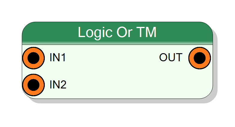
Time-multiplexed bitwise OR operation. Performs logical OR between two TM inputs or one TM input and a scalar mask. Output is 1 when at least one corresponding input bit is 1. Supports TM factors from 2 to 32. Pure combinational logic (zero latency).
Introduction
This block performs a bitwise OR operation on time-multiplexed (TM) data streams. Supports two operation modes:
- TM mode: Both IN1 and IN2 are TM, element-wise OR per phase
- STD mode: IN1 is TM, IN2 is scalar mask applied to all phases
The operation is purely combinational with zero clock latency:
$$ \mathrm{OUT}(n) = \mathrm{IN1}(n) \lor \mathrm{IN2}(n), $$
where $\lor$ represents the logical OR operation.
Pin Description
Input Size × TM Factor
Second input data, TM or scalar.
- TM mode: Width =
Input Size × TM Factor - STD mode: Width =
Input Size
Input Size × TM Factor
Properties
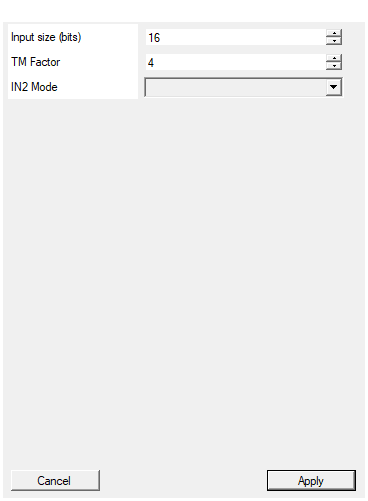
Set the size of each input in bits
Number of bits per input sample. Range: 1 – 16384.Default: 16
Range: 1 – 16384
Time Multiplexing factor (number of phases)
Time-multiplexing factor. Range: 2 – 32.Default: 4
Range: 2 – 32
Specify if IN2 input is Time Multiplexed (TM) or Standard (STD). STD mode allows using a constant mask applied to all TM phases.
Input mode for IN2: TM or STD (scalar).Default: TM
Options: TM STD
Functional description
The component implements a bitwise OR gate in VHDL, replicated N times (where N = TM Factor) to support time-multiplexed data streams.
For each TM phase and each bit position:
$$ y[i] = x_1[i] \lor x_2[i], $$
where $\lor$ represents the logical OR operation.
Truth table:
| IN1 | IN2 | OUT |
|---|---|---|
| 0 | 0 | 0 |
| 0 | 1 | 1 |
| 1 | 0 | 1 |
| 1 | 1 | 1 |
Timing
Purely combinational with zero latency.
Typical use cases
- Signal combination and multiplexing
- Multi-channel trigger logic (any channel triggers)
- Building complex boolean functions