
Majority Sync
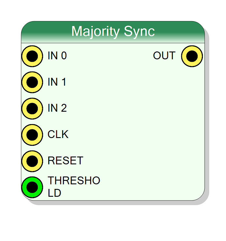
Synchronous majority voting logic gate with programmable threshold. Returns 1 if the number of active inputs meets or exceeds the threshold. Configurable from 2 to 8 inputs with dynamic threshold control. Registered output (1 cycle latency).
Introduction
This block implements a synchronous majority voting logic gate with programmable threshold. Unlike the combinational majority gate, this version:
- Has a registered (synchronous) output with 1 clock cycle latency
- Supports dynamic threshold programming via the THRESHOLD input
- Requires CLK and RESET signals
Operation:
- Output = 1 if the number of active inputs ≥ THRESHOLD
- Output = 0 otherwise
- Output is registered on the rising edge of CLK
The number of inputs is configurable from 2 to 8 at component creation time.
For $N$ inputs with $M$ inputs at logic 1 and threshold $T$:
$$ \mathrm{OUT}[n+1] = \begin{cases} 1 & \text{if } M[n] \geq T[n] \ 0 & \text{otherwise} \end{cases} $$
where $n$ represents the current clock cycle and $n+1$ the next.
Pin Description
Properties
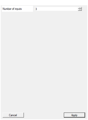
Set the number of input signals
Number of input signals for threshold voting. Range: 2 to 8. This property is set during block creation and defines the maximum possible threshold value.Default: 3
Range: 2 – 8
Functional description
The component implements synchronous majority voting logic with programmable threshold in VHDL. It counts the number of active (1) inputs and compares it to the THRESHOLD:
$$ y[n+1] = \begin{cases} 1 & \text{if } \sum_{i=0}^{N-1} x_i[n] \geq T[n] \ 0 & \text{otherwise} \end{cases} $$
where:
- $x_i[n]$ → input bit $i$ at clock cycle $n$
- $T[n]$ → threshold value at clock cycle $n$ (1 to N)
- $y[n+1]$ → registered output at clock cycle $n+1$
- $N$ → total number of inputs (2-8)
Example with 5 inputs
If THRESHOLD = 3:
- Inputs =
01011(3 ones) → OUT = 1 (meets threshold) - Inputs =
00101(2 ones) → OUT = 0 (below threshold) - Inputs =
11111(5 ones) → OUT = 1 (exceeds threshold)
Dynamic threshold programming
The THRESHOLD input allows runtime reconfiguration of the voting rule:
- THRESHOLD = 1: OR-like behavior (any input active → output 1)
- THRESHOLD = N: AND-like behavior (all inputs active → output 1)
- THRESHOLD = ⌈N/2⌉: Traditional majority voting
Mathematical background
Programmable threshold majority voting extends basic majority logic with runtime flexibility. Applications include:
- Adaptive fault tolerance: Adjusting redundancy requirements dynamically
- Configurable trigger logic: Varying coincidence requirements
- M-of-N voting: Generalized majority (M out of N must agree)
- Dynamic reliability: Changing voting rules based on operating conditions
Timing
The component has 1 clock cycle latency due to output registration:
| Property | Latency (clock cycles) |
|---|---|
| Majority Sync | 1 |
The output is updated on the rising edge of CLK.
Typical use cases
- Programmable trigger coincidence logic
- Adaptive redundancy in safety systems
- Configurable multi-detector voting
- Dynamic threshold adjustment for noise conditions
- M-of-N voting schemes in distributed systems