
RF Complex Accumulator (integrate-and-dump)
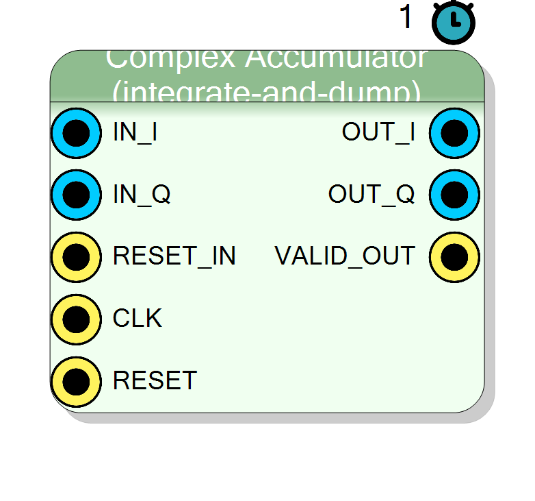
Complex integrate-and-dump: sums N consecutive I/Q samples, latches the running sum to the output and pulses VALID_OUT, then clears and restarts. Typical use: coherent integration / matched-filter accumulation to raise SNR before a decimated readout.
Introduction
The Complex Accumulator (integrate-and-dump) maintains a running sum of
the incoming complex stream and dumps it every N samples:
for k = 0 .. N-1: sum += IN[n-k]
OUT = sum (latched on the dump cycle)
VALID_OUT = 1 (one clock, on the dump cycle)
sum <- 0 (restart)
Summing N coherent samples of a signal buried in zero-mean noise improves
SNR by up to 10*log10(N) dB, which is why integrate-and-dump is the
front end of most coherent detectors and lock-in style measurements.
N is fixed at synthesis time by the Accumulation Length N property.
The plugin bakes N in as an internal constant on the len port; the HLS
core also supports a run-time len but here it is tied to the constant.
Pin Description
'0' when unused.
Properties
Bit width of each I/Q input (signed).
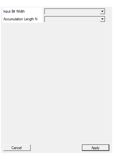
Bit width of each signed I / Q input sample. Range 4 to 32, default 16.Default: 16
Options: 4 5 6 7 8 9 10 11 12 13 14 15 16 17 18 19 20 21 22 23 24 25 26 27 28 29 30 31 32
Number of samples per integrate-and-dump. Output width = InputSize + ceil(log2(N)).
Accumulation lengthN (samples per integrate-and-dump). Selectable
from 16, 32, 64, 128, 256, 512, 1024, 2048, 4096, 8192, default
256. Output width = InputSize + ceil(log2(N)).
Default: 256
Options: 16 32 64 128 256 512 1024 2048 4096 8192
Usage
Stateful / feedback behaviour
This is a stateful block. The C++ core keeps static feedback
registers that persist between samples:
static acc_t sum_i, sum_q; // running complex sum
static len_t cnt; // sample counter, 0 .. N-1
static acc_t out_i_reg, out_q_reg; // latched (held) output
Each clock the core computes next_sum = sum + IN and next_cnt = cnt+1.
When next_cnt == N it dumps: the new sum is latched into the output
registers, VALID_OUT goes high for that one cycle, and sum/cnt are
cleared to zero so the next window starts fresh. On all other cycles the
output registers hold their previous value and VALID_OUT is low.
Reset behaviour
There are two independent resets:
RESET— the HLS synchronous reset (ap_rst). Clears allstaticstate (sum, counter and the latched output) on assertion.RESET_IN— a data-path input pin (ap_none, tie to'0'when unused). When high it clearssumandcntto zero on that cycle without dumping (VALID_OUTstays low and the held output is not updated). Use it to realign the integration window to an external event or gate.
Bit widths
IN_I,IN_Q: signedInputSizebits.OUT_I,OUT_Q: signedInputSize + ceil(log2(N))bits.VALID_OUT: 1 bit.
The ceil(log2(N)) growth guarantees the sum of N full-scale samples
never overflows the accumulator.
Latency and throughput
#pragma HLS PIPELINE II=1: accepts one input pair per clock.- The output is only meaningful on the cycle
VALID_OUTis high; it then holds until the next dumpNsamples later. - All ports use
ap_none;lenusesap_stable. #pragma HLS INTERFACE ap_ctrl_none port=return: no block-level control.
Typical applications
- Coherent integration after a mixer to pull a tone out of noise.
- Matched-filter / lock-in accumulation over a fixed dwell.
- Block averaging feeding a slower downstream reader (use
VALID_OUTas the sample-valid strobe; divide byNdownstream for a mean).
Resources & Timing
-
Latency: 1 clock cycle (result valid on the VALID_OUT strobe)
-
Throughput: 1 input sample per clock (II=1); one output every N samples
Two accumulators plus a counter; no multipliers, no BRAM. Stateful (uses static feedback registers for the sum, counter and held output). One output sample every N clocks, flagged by VALID_OUT.