QDC
Programmable charge–to–digital converter (QDC) that integrates the amplitude of a sampled input pulse over a user–defined window, applies baseline subtraction, digital gain and offset, performs pile-up rejection, and outputs a 16-bit energy word together with several status flags. The core is fully synchronous and single-clock-cycle streaming (II = 1).
Introduction
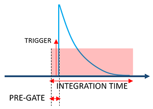
The QDC block calculates the total charge of a detector pulse by
summing consecutive N samples of the input stream DATA_IN. The
integration window is started by the rising edge of TRIGGER and
can optionally include a programmable number of pre-samples
(PRE_TRIGGER).
Key features
- 16-bit to 32-bit input / 16-bit to 32-bit output.
- Programmable integration length, pre-trigger depth, pile-up inhibition, digital gain and offset.
- Real-time pile-up rejection with optional enable.
- One-cycle throughput, deterministic latency.
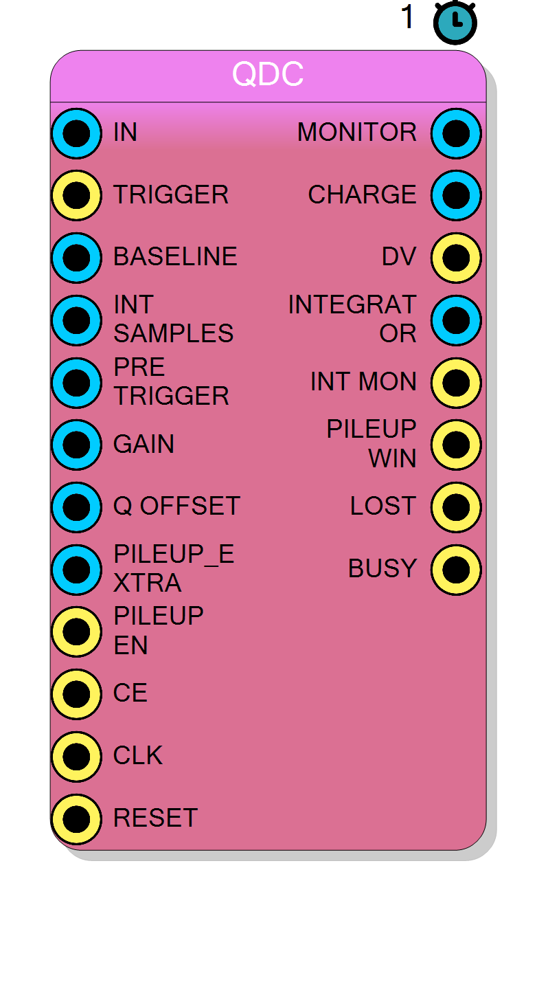
Pin Description
Width =
Wordsize bits. Values are not inverted internally
(negative pulses must be pre-processed).
If asserted while
BUSY is high and pile-up rejection is
enabled, the event is discarded and PILEUP_WIN is raised.
1 … 65 535. Programmable through the control bus; stable during run time.
$$E_\text{raw} = Q \cdot \frac{\texttt{GAIN}}{2^{16}}$$
Setting
GAIN = 0xFFFF leaves $Q$ unchanged.
DATA_IN shifted by PRE_TRIGGER).
DV is high.
CHARGE
word.
BUSY while the FSM is in state D_INTEGRATE).
Q) for debugging/monitoring
purposes.
DV or end of
pile-up window. Indicates that the core cannot accept a new
valid event.
Properties
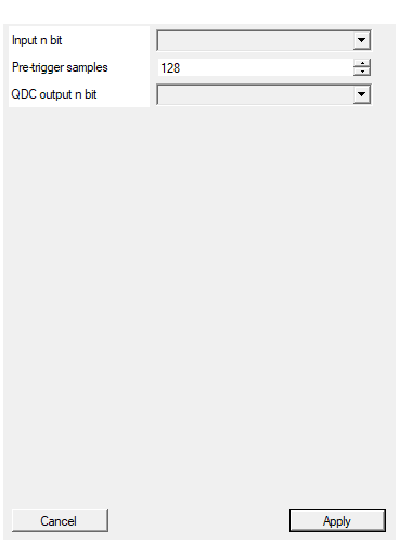
Set the analog channel word size in bits
Width (in bits) ofDATA_IN. Affects accumulator width and
resource utilisation. Must be the same for input and baseline.
Default: 16
Options: 16 24 32
Set the number of max number of pre-trigger samples
Maximum size of the pre-trigger circular buffer (PRE_LEN)
compiled into the core. Limits the range of PRE_TRIGGER.
Default: 128
Range: 1 – 4095
Set the output word size in bits
Width (in bits) ofCHARGE. Hard-coded to 16 in the current
release; changing it requires regenerating the RTL.
Default: 16
Options: 16 24 32
Operating principle
Let the digitised input samples be denoted by
$x[n] = \texttt{DATA\_IN}[n] - \texttt{BASELINE}$.
During an integration window of length $N_\text{int}$
(set by INT_SAMPLES) the accumulated charge is
$$ Q = \sum_{k=0}^{N_\text{int}-1} x[n-k-N_\text{pre}], $$
where $N_\text{pre}$ (PRE_TRIGGER) is the number of samples that
precede the trigger and are therefore read from the circular
pre-buffer.
The final 16-bit energy word is
$$ E = \operatorname{sat}_{16} \left( \frac{Q \cdot \texttt{GAIN}}{2^{16}} + \texttt{Q\_OFFSET} \right), $$
where sat₁₆ denotes saturation to the unsigned 16-bit range
$[0,2^{16}-1]$.
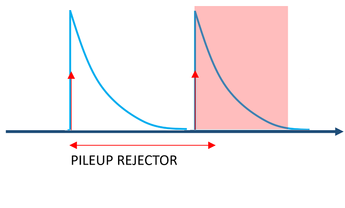
Pile-up rejection
If PILEUP_EN is high, every subsequent trigger that arrives
within the inhibition window PILEUP_EXTRA aborts the current
integration, sets PILEUP_WIN, and restarts the
rejection counter. When the counter expires the state machine
returns to idle.
Timing
The core is fully pipelined with an initiation interval of 1
clock cycle.
Latency from the first sample that belongs to the integration
window to the assertion of DV is
$$ L = N_\text{int} + 2 ;\text{cycles}. $$
- 1 cycle:
CHECKVALUEstage - 1 cycle:
HIST(output-formatting) stage
Additional fixed delay introduced by the pre-buffer is
PRE_TRIGGER cycles, but this does not affect system latency
because those samples are stored in parallel with the incoming
stream.
Images