
TM Signal Replicator
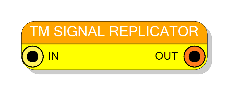
Replicates a single scalar std_logic_vector signal to all phases of a time-multiplexed (TM) bus. Takes one input signal and broadcasts it to N TM phases, creating a TM output where all phases carry identical data. Supports TM factors from 2 to 32. Pure combinational logic with zero latency.
Introduction
This block replicates a single scalar signal to all phases of a time-multiplexed (TM) bus. It broadcasts one input to N identical TM phases, useful for applying the same value to all channels in a TM processing pipeline.
The operation is purely combinational with zero clock latency:
$$ \mathrm{OUT}[W \times (i+1) - 1 : W \times i] = \mathrm{IN}, \quad i = 0 \ldots N-1 $$
where $W$ is the signal size and $N$ is the TM factor. All TM phases receive the same input value.
Pin Description
Output TM bus, always TM. Width: Signal Size × TM Factor TM Factor: Configurable (2 to 32)
All TM phases carry identical copies of the input signal. Bit layout: OUT[(i+1)×W-1 : i×W] = IN for all i
Output is combinational (zero latency).
Properties
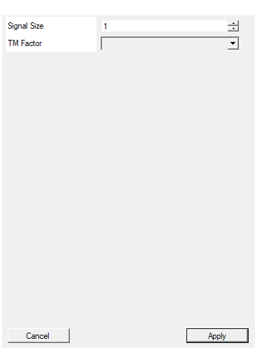
Set the size in bits of the input signal
Width in bits of the input signal (1 to 16384 bits). This is also the width of each TM phase in the output. Total output width = Signal Size × TM Factor.Default: 1
Range: 1 – 16384
Select the TM Factor for the output (number of replications)
Number of TM phases (2 to 32) for the output. The input signal is replicated this many times to create the TM output bus.Default: 4
Options: 2 4 8 16 32
Functional description
The TM Signal Replicator copies a single scalar input to all N phases of the output TM bus. This creates a TM signal where every phase carries identical data.
Replication operation
For a TM factor of $N$ and signal size $W$:
$$ \forall i \in [0, N-1]: \quad \mathrm{OUT}[(i+1)W - 1 : iW] = \mathrm{IN}[W-1:0] $$
The input signal is replicated $N$ times: $$ \mathrm{OUT} = \underbrace{\mathrm{IN} ,||, \mathrm{IN} ,||, \ldots ,||, \mathrm{IN}}_{N \text{ times}} $$
where $||$ denotes concatenation.
Example with TM Factor = 4, Signal Size = 16
Input: IN = 0xABCD (16 bits)
TM output (64 bits): $$ \mathrm{OUT}[63:0] = \texttt{0xABCD_ABCD_ABCD_ABCD} $$
Bit layout:
OUT[63:48] = 0xABCD (Phase 3)
OUT[47:32] = 0xABCD (Phase 2)
OUT[31:16] = 0xABCD (Phase 1)
OUT[15:0] = 0xABCD (Phase 0)
All four TM phases carry the same value.
Use case examples
-
Broadcasting a constant to all channels:
- Apply same threshold to all ADC channels
- Distribute common configuration value
-
Creating TM-compatible control signals:
- Convert scalar enable to TM enable (all phases)
- Broadcast reset signal to TM processing chain
-
Parameter distribution:
- Share single parameter across parallel processing paths
- Common offset/gain application
Timing
The component is purely combinational with zero latency:
| Property | Latency (clock cycles) |
|---|---|
| TM Signal Replicator | 0 |
The TM output is available immediately in the same clock cycle as the input.
Typical use cases
- Broadcasting threshold values to all TM channels
- Converting scalar parameters to TM format
- Distributing control signals across TM processing chains
- Creating TM constants from scalar values
- Synchronous parameter application to parallel channels
Important notes
- All TM phases receive identical data - no phase-specific variation
- Input is a scalar signal, output is TM
- No clock required - purely combinational wiring
- Complementary operation: use TM Phase Extractor to extract a single phase