

RF Baseband DDC (SSR4) TM
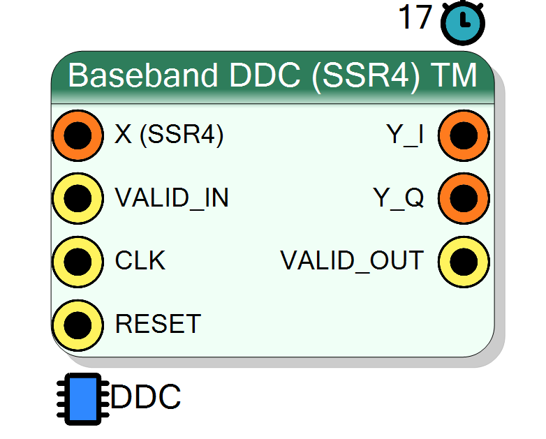
TM_FACTOR independent KriaTest SSR4 down-converters on one time-multiplexed bus (one per antenna / ADC), each with its own 32-bit NCO register.
Introduction
Same arithmetic as baseband_ddc (the KriaTest DDC loop body), replicated
per slot with independent state. Repo TM contract: slot s occupies bits
[(s+1)*W-1 : s*W] of every bus, one VALID_IN / VALID_OUT for the
whole word.
Pin Description
Properties
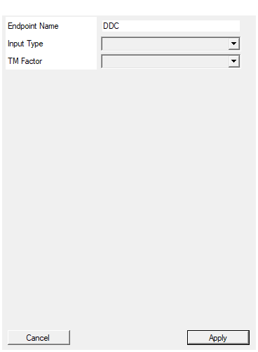
Name of the register endpoint. Registers are REG_
DDC).
Default: DDC
Real: one ADC per slot (DDC_REAL_INPUT=1). Complex: I/Q per slot from an external mixer (DDC_REAL_INPUT=0).
Real (DDC_REAL_INPUT=1) or Complex (DDC_REAL_INPUT=0) per slot.
Default: Real
Options: Real Complex
Number of independent DDC slots on the bus (TM_FACTOR). Resources scale linearly.
Number of slots (TM_FACTOR): 2, 4 or 8. Resources scale linearly.
Default: 2
Options: 2 4 8
Usage
Registers (endpoint = EndpointName)
| register | access | meaning |
|---|---|---|
CTRL |
W | b1 clear (level, all slots) |
PHASE_INC0 .. PHASE_INC<TM-1> |
W | NCO increment of each slot |
Slot widths: X / X_I / X_Q 64 bit (4 int16 lanes, lane 0 oldest),
Y_I / Y_Q 16 bit.
Resources & Timing
-
Latency: 17 clocks
-
Throughput: TM_FACTOR SSR4 groups per clock
TM=2: Real 76 DSP / 32 BRAM18, Complex 92 DSP (Vitis HLS 2022.2, xck26, 3.39 ns estimated). Verified per slot against the KriaTest C function (tb/kria_ddc, cases tm2_real / tm2_iq).