
IFFT
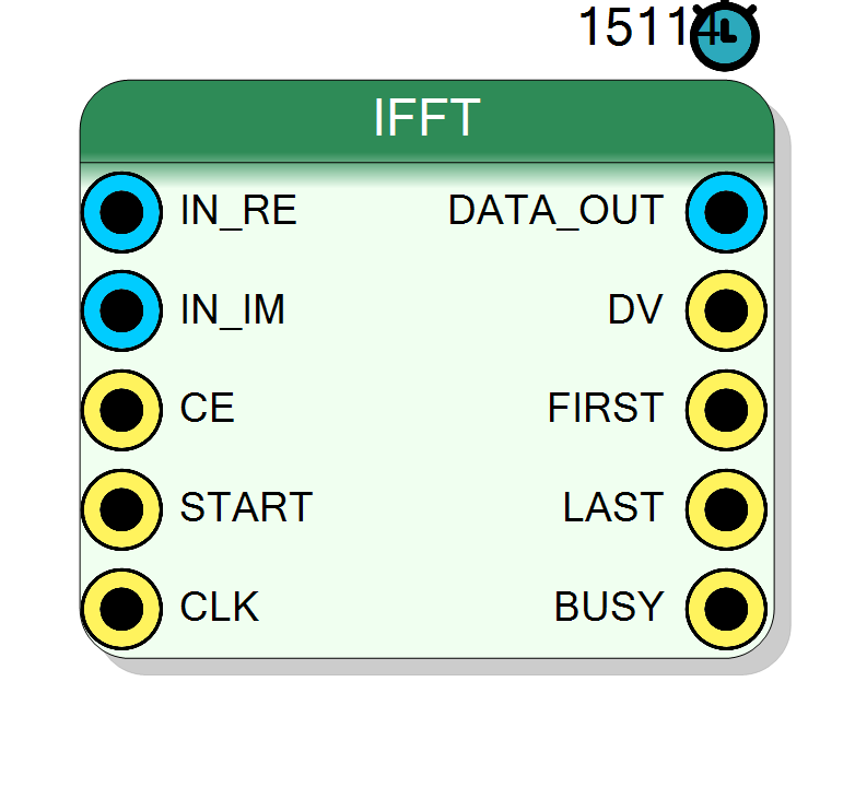
Inverse Fast Fourier Transform engine built on top of the Xilinx FFT IP core in inverse mode: sequential complex spectrum in (one bin per clock), REAL time-domain signal out. Dual of the FFT block, with the same four algorithm architectures (Pipelined, Radix-4, Radix-2, Radix-2 Lite), configurable spectrum width and saturating output width.
Introduction
The block computes the inverse Discrete Fourier Transform of a complex spectrum, reconstructing the time-domain sequence:
$$ x[n] = \frac{1}{N}\sum_{k=0}^{N-1} X[k] \cdot e^{+j2\pi kn/N}, \quad n = 0, 1, \ldots, N-1 $$
The spectrum enters sequentially, one bin per clock on IN_RE / IN_IM:
a START pulse marks the cycle carrying bin 0, and the following $N-1$
CE-gated cycles carry bins $1 \ldots N-1$ in natural order. The
reconstructed signal leaves as a sequential burst (one sample per clock)
on DATA_OUT, framed by FIRST / LAST with DV_OUT per sample.
Only the real part of the reconstruction is emitted: the input spectrum is expected to be conjugate-symmetric ($X[N-k] = X^*[k]$, automatic when it comes from an FFT of a real signal). Any residual imaginary part is discarded.
The internal datapath is the Xilinx FFT IP core, switched to inverse mode at startup through its configuration channel. The Algorithm options trade off throughput, latency and resource usage exactly as in the forward block.
Pin Description
Properties
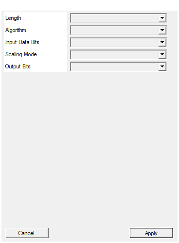
Select length of the inverse FFT transform
Transform length $N$ (128 .. 16384, power of 2). Must match the spectrum source.Default: 4096
Options: 128 256 512 1024 2048 4096 8192 16384
xfft engine. Pipelined Streaming: fastest, largest. Radix-4 Burst: ~4x smaller, transform ~(N/4)*log4(N) clocks. Radix-2 Burst: smaller again, ~(N/2)log2(N) clocks. Radix-2 Lite: smallest (time-shared butterfly), ~Nlog2(N) clocks.
- Pipelined: highest throughput, largest area.
- Radix-4: one radix-4 engine, $\approx (N/4)\log_4 N$ clocks. Recommended default.
- Radix-2: one butterfly, $\approx (N/2)\log_2 N$ clocks.
- Radix-2 Lite: time-shared butterfly, $\approx N\log_2 N$ clocks, smallest footprint.
Default: Radix-4
Options: Pipelined Radix-4 Radix-2 Radix-2 Lite
Bit width of each spectrum component RE/IM (8-32 bits, signed). Set 32 to chain directly the 32-bit OUT_RE/OUT_IM of FFT, FFT Windowed or FFT TM Triggered.
Spectrum component width RE/IM (8..32, signed). Set 32 to chain the 32-bit FFT outputs directly. Match the source: e.g. an unscaled FFT of a 16-bit signal produces $16 + \log_2 N + 1$ bits.Default: 16
Options: 8 9 10 11 12 13 14 15 16 17 18 19 20 21 22 23 24 25 26 27 28 29 30 31 32
Scale (default): output divided by N with rounding - reconstructs the original amplitude after an unscaled FFT. No Scaling: output = N*x, full bit growth (saturating).
- Scale (default): output divided by N (round half up) - reconstructs the original amplitude after an unscaled FFT.
- No Scaling: output = N*x, full bit growth (saturating).
Default: Scale
Options: Scale No Scaling
Width of DATA_OUT samples (saturating). Auto: InputBits in Scale mode, InputBits+log2(N)+1 (max 32) otherwise. Set 16 to get back the original 16-bit signal after an unscaled FFT -> IFFT (Scale) chain.
Width of DATA_OUT (saturating). Auto follows ScalingMode (InputBits wide in Scale mode). Set an explicit value - e.g. 16 - to force the bus width regardless of InputBits.Default: Auto
Options: Auto 8 9 10 11 12 13 14 15 16 17 18 19 20 21 22 23 24 25 26 27 28 29 30 31 32
Chaining from the FFT blocks
The natural wiring from the FFT or FFT TM Triggered block is:
OUT_RE→IN_RE,OUT_IM→IN_IMFIRST→START(marks bin 0)DV→CE(gates the bin stream)
Because the upstream burst is $N$ contiguous bins, the load happens at
line rate; the block then transforms and emits the burst. BUSY stays
high from START until the last output sample; a new START while
BUSY = 1 is ignored, so back-to-back operation is safe when both
blocks use the same Algorithm.
Getting the original amplitude (and width) back
The core is unscaled, so the raw inverse has a gain of $N$. With
ScalingMode = Scale (default) the output is divided by $N$ with
round-half-up: if the spectrum comes from an unscaled FFT of a signal
$x$, the output is $x$ itself. Output Bits then forces the width of
DATA_OUT (saturating): set 16 after an unscaled FFT of a 16-bit
signal to get the original 16-bit bus back.
Verified in simulation (N = 1024, Radix-4, 16-bit spectrum of a two-tone + noise signal, three consecutive frames): the reconstruction is bit-exact (error = 0 LSB on every sample) when the spectrum is an exact integer DFT; through a full hardware FFT → IFFT chain the error is bounded by the FFT rounding (~1 LSB).
Round-trip configuration summary
| Block | Setting |
|---|---|
| FFT (or FFT TM Triggered) | unscaled output, 16-bit input |
| IFFT | InputBits = spectrum width, ScalingMode = Scale, Output Bits = 16 |
Timing
- Load: $N$ clocks (
CE-gated, from theSTARTpulse). - Transform: same engine cycle counts as the forward block - Pipelined: hidden behind the load; Radix-4: $\approx \tfrac{N}{4}\log_4 N$; Radix-2: $\approx \tfrac{N}{2}\log_2 N$; Radix-2 Lite: $\approx N\log_2 N$.
- Unload: $N$ clocks (the output burst).
The burst engines cannot accept a new spectrum while transforming:
wait for BUSY = 0 (automatic when chained after a triggered FFT with
the same Algorithm).
Algorithm : area vs speed
| Algorithm | Area (DSP) | Transform time (clocks) |
|---|---|---|
| Pipelined | largest, ~20-40 | hidden behind the load |
| Radix-4 | ~9-12 | $\approx \tfrac{N}{4}\log_4 N$ |
| Radix-2 | ~3-4 | $\approx \tfrac{N}{2}\log_2 N$ |
| Radix-2 Lite | ~2-3, least logic | $\approx N\log_2 N$ |