ISIS PSD COEF TM
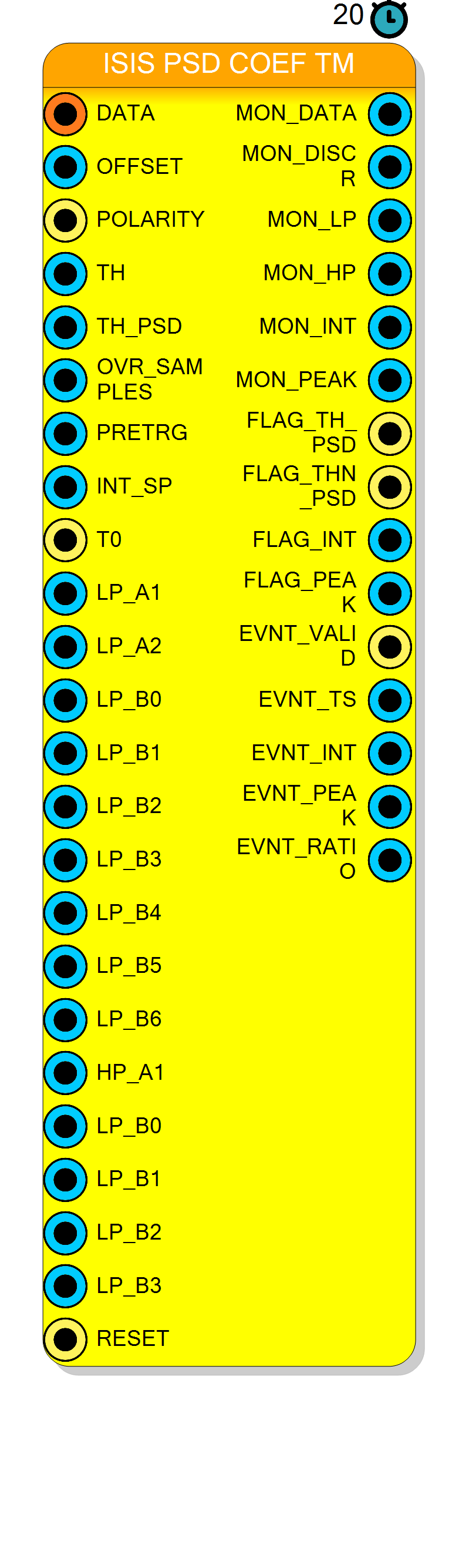
Runtime-programmable variant of the ISIS PSD TM block. It performs the same time-multiplexed discrimination, shaping, charge integration and event building, but the nine coefficients of the low-pass shaping section are brought out as pins instead of being compiled into the core, so the pulse-shape filter can be retuned without re-synthesising the HLS IP.
Introduction
Principle of Operation
ISIS PSD COEF TM is generated from isispsdcoeff.cpp, which is isispsd.cpp with the
filter coefficients lifted from compile-time constants to function arguments. Everything
else — the 4-lane time-multiplexed input, the lane-average discriminator, the PSD threshold
with its over-threshold counter, the 128-entry pre-trigger delay line, the four parallel
integrators and the event output — is identical. Read the ISIS PSD TM page first; this
page documents only what is different.
The low-pass section is still the scattered look-ahead form of a 2nd-order IIR,
$$ y[n] ;=; \sum_{k=0}^{6} b_k,x[n-k] ;-; a_1,y[n-3] ;-; a_2,y[n-6] $$
but now $a_1, a_2$ arrive on LP_A1, LP_A2 and $b_0 \dots b_6$ on LP_B0 … LP_B6.
Each coefficient pin is 18 bit wide and carries an ap_fixed<18,2> value: signed, two
integer bits, sixteen fractional bits. To program a real coefficient $c$ drive the two’s
complement of
$$ \mathrm{raw} ;=; \mathrm{round}!\left(c \times 65536\right), \qquad -2 \le c < 2 $$
so the resolution is $2^{-16} \approx 1.5\times10^{-5}$.
Pin Description
x"0000".
'0'.
ap_stable. Default when left open: x"01FF" (511).
MON_HP.
ap_stable. Default when left open: x"000F" (15).
TH_PSD required to arm an event
(strict comparison). One unit = 4 input samples.
ap_stable. Default when left open: x"000A" (10).
ap_stable. Default when left open: x"000A" (10).
4 × INT_SP samples.
ap_stable. Default when left open: x"00A0" (160).
'0'.
ap_fixed<18,2>: raw = round(a1 × 65536), range -2 … +2.
Reference value -1.691126416184245.
ap_fixed<18,2>. Reference value 0.7213785295739619.
ap_fixed<18,2>.
Reference value 0.00093575.
Low-pass feed-forward coefficient $b_6$ ($x[n-6]$). Reference value 0.00075267.
Note: the symbol carries LP_B0 … LP_B3 twice — the second group was meant to be
HP_B0 … HP_B3.
highpassfilter() ignores its
coefficient arguments and uses the constant -0.8599680957679054 instead.
ap_fixed<18,2>.
Reference value 0.00093575.
ap_rst). Left open it is tied to the project global reset.
TH, otherwise 0.
LP_*.
TH_PSD.
MON_HP is above TH_PSD (level).
OVR_SAMPLES
clocks and a new event is armed.
EVNT_* pins
(slots are drained in the order 0, 1, 2, 3; at most one per clock).
timestamp + 4 × PRETRG, where the internal counter
advances by 4 each clock and is cleared by T0.
INT_SP clocks.
Internal: (EVNT_INT << 8) / EVNT_PEAK (Q8). External: the constant 1.
Properties
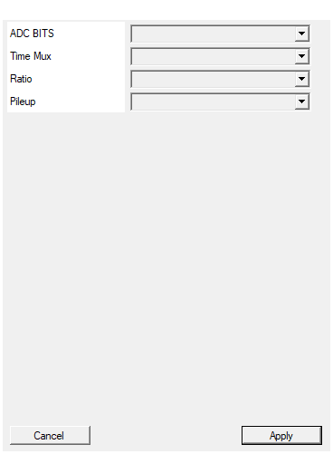
Set the number of raal bits of the board ADC
Nominal number of ADC bits. It does not change the generated core — it only enters the MD5 that names the HLS IP. Values: 12, 13, 14. Default: 12.Default: 12
Options: 12 13 14
Set number of samples for each clock cycle
Samples carried per clock onDATA. The core is hard-wired to four lanes, so the combo
offers a single value. Changing it rebuilds the symbol. Default: 4.
Default: 4
Options: 4
Set if make division internal or external
Where the integral/peak division happens.
| Value | Effect |
|---|---|
External |
EVNT_RATIO = 1; declared latency 20 clocks |
Internal |
EVNT_RATIO = (EVNT_INT << 8) / EVNT_PEAK; declared latency 55 clocks |
Part of the HLS IP name, so both variants can coexist. Changing it rebuilds the symbol. Default: External.
Default: External
Options: External Internal
Set if stop integral on pileup or use a secondary integrator to process events
Fate of an integration that is still running when a new event is armed:Stop Integral terminates and commits it immediately, Continue lets it run the full
INT_SP. The property is not part of the HLS IP name, and its shipped default
(External) is not one of the combo values — with it the core behaves as Continue.
Default: External (behaves as Continue).
Default: External
Options: Stop Integral Continue
⚙️ Detailed Operation
What changed with respect to ISIS PSD TM
| ISIS PSD TM | ISIS PSD COEF TM | |
|---|---|---|
| top C function | isispsd |
isispsd_coeff |
| low-pass coefficients | compiled in | pins LP_A1, LP_A2, LP_B0…LP_B6 |
| high-pass coefficients | compiled in | compiled in (see the alert below) |
| pins | 25 | 39 |
| properties | identical (adcbits, TimeMultiplexing, Ratio, Pileup) |
identical |
| declared latency | 20 / 55 clocks | 20 / 55 clocks |
Everything else — lane unpacking (lane 0 in the low bits, oldest sample), the
(x0+x1+x2+x3) >> 2 lane average compared with TH, the 6553-high discriminator pulse,
the OVR_SAMPLES consecutive-clock condition on TH_PSD, the PRETRG delay line limited to
127 clocks, the four-slot integrator with its Stop Integral / Continue pile-up modes, the
timestamp + 4 × PRETRG event stamp and the Internal / External ratio — behaves exactly
as described on the ISIS PSD TM page.
Reference coefficient set
The values that are hard-coded in the non-programmable block are the natural starting point for the programmable one:
| Pin | Reference value | 18-bit raw (round(c × 65536)) |
|---|---|---|
LP_A1 |
-1.691126416184245 | -110830 → 0x24F12 (two’s complement) |
LP_A2 |
0.7213785295739619 | 47276 → 0x0B8AC |
LP_B0 |
0.00093575 | 61 → 0x0003D |
LP_B1 |
0.00364298 | 239 → 0x000EF |
LP_B2 |
0.00699309 | 458 → 0x001CA |
LP_B3 |
0.00838898 | 550 → 0x00226 |
LP_B4 |
0.00644455 | 422 → 0x001A6 |
LP_B5 |
0.00309409 | 203 → 0x000CB |
LP_B6 |
0.00075267 | 49 → 0x00031 |
The sign convention is the one used in the source: the two feedback terms are subtracted
(- a1·y[n-3] - a2·y[n-6]), so LP_A1 is negative for this reference set.
The high-pass section is not programmable
isispsd_coeff() declares the arguments hp_a1, hp_b0, hp_b1, hp_b2, hp_b3 and
passes them to highpassfilter(), but the body of highpassfilter() never uses them —
it still reads the local constant arrays:
const t_filter_coef hp_a[] = { 1, -0.8599680957679054 };
const t_filter_coef hp_b[] = { 0.97547839, -0.0478406, -0.04549434, -0.88214345 };
...
hp_y = hp_b[0]*x + hp_b[1]*hp_x1 + hp_b[2]*hp_x2 + hp_b[3]*hp_x3 - hp_a[1]*hp_y3;
Designing a coefficient set
The shaping chain turns a rectangular discriminator pulse into a signal whose amplitude grows
with the width of that pulse; TH_PSD then separates the species. When you retune the
low-pass section, keep in mind:
- the section is written in scattered look-ahead form, so the feedback taps are at $n-3$ and $n-6$, not at $n-1$ and $n-2$. A conventional biquad $(a_1, a_2)$ pair cannot be dropped in unchanged — it must be transformed to the 3-fold-scattered equivalent, which is also why there are seven $b_k$ for a 2nd-order response;
- the accumulator type is
ap_fixed<24,16>, i.e. 16 integer bits with 8 fractional bits, so a set with a large DC gain will saturate before the output reachesMON_LP; - the coefficients are declared
ap_stable: they are meant to be static during acquisition. Change them while the input is quiet.
Generated hardware and build
Identical to ISIS PSD TM except for the top function name:
- source written to
HLS/<unique>/isispsd_coeff.cppwith theINTERNAL_RATIO/STOP_INTEGRAL_ON_PILEUPdefines prepended; hls_compile.tclrunscsynth_designwithset_directive_top -name <unique> isispsd_coeff, a clock period offloor(1000000 / AcquisitionClockFreq)ns (4 ns on the NI DAQ121’s 250 MHzCLK_ACQ), and merges the VHDL intoHDL/pcores/<unique>.vhd;- the IP name is
isispsd_coeff_<8 letters>, the letters being an MD5 of (component name, ADC BITS, Time Mux, Ratio) —Pileupis not in the hash, so two instances differing only in that property share one IP; ap_clkis tied to the acquisition clock (there is no CLK pin),ap_rstto the global reset whenRESETis left open;- the block requires a license and is offered only on the NI DAQ121
(board GUID
10B906F8-657F-4C13-A697-4637BE6DEC27); CompileHDLaborts silently when Vitis HLS is not found and the build is not remote.
There is no CompileMMC / CompileSDK content: the block has no software registers,
so the coefficients must be driven from constant or register blocks on the schematic.
Resources & Timing
-
Latency: Declared block latency: 20 clocks with Ratio = External, 55 clocks with Ratio = Internal
-
Throughput: One 64-bit word (4 samples) per clock, II = 1; at most one event per clock on EVNT_VALID
- 4 concurrent integrators; a 5th simultaneous event is dropped without any flag.
- 128-entry × 64-bit pre-trigger delay line, so
PRETRGmust stay below 128. - Coefficient pins are
ap_fixed<18,2>(raw = value × 65536); filter statesap_fixed<24,16>. - Nine of the fourteen coefficient inputs are effective; the five high-pass ones are not.