
TM Phase Extractor
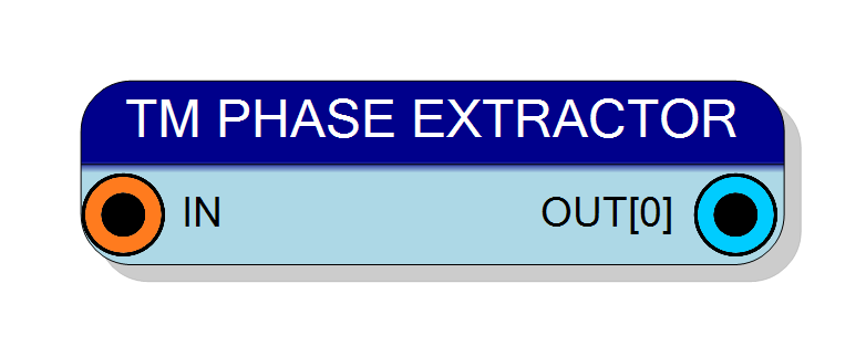
Extracts a single specific phase from a time-multiplexed (TM) bus and outputs it as a scalar std_logic_vector signal. Selects one TM phase using a configurable phase index (0 to TM_FACTOR-1). Supports TM factors from 2 to 32. Pure combinational logic with zero latency.
Introduction
This block extracts a single specific phase from a time-multiplexed (TM) bus and outputs it as a scalar signal. Unlike the TM Splitter which extracts all phases, this component selects only one phase based on the Phase Select property.
The operation is purely combinational with zero clock latency:
$$ \mathrm{OUT} = \mathrm{IN}[W \times (P+1) - 1 : W \times P] $$
where $W$ is the signal size per phase and $P$ is the selected phase index (0 to TM_FACTOR-1).
Pin Description
Input TM bus, always TM. Width: Signal Size × TM Factor TM Factor: Configurable (2 to 32)
Bit layout: Phase i = IN[(i+1)×W-1 : i×W]
Output scalar signal, std_logic_vector. Width: Signal Size (same as one TM phase)
Contains the data from the selected TM phase (Phase Select property). Pin label shows: “OUT[P]” where P is the selected phase number.
Output is combinational (zero latency).
Properties
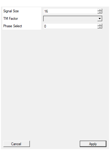
Set the size in bits of each TM phase
Width in bits of each TM phase (1 to 16384 bits). The output will have this same width. Total input width = Signal Size × TM Factor.Default: 16
Range: 1 – 16384
Select the TM Factor of the input
Number of TM phases in the input (2 to 32). This determines the valid range for Phase Select (0 to TM Factor - 1).Default: 4
Options: 2 4 8 16 32
Select which TM phase to extract (0 to TM_FACTOR-1)
Index of the TM phase to extract (0 to TM Factor - 1). Phase 0 corresponds to the LSBs of the TM bus. This is a compile-time constant and cannot be changed at runtime.Default: 0
Range: 0 – 31
Functional description
The TM Phase Extractor selects a single phase from the input TM bus based on the Phase Select property and outputs it as a scalar signal.
Extraction operation
For a TM factor of $N$, signal size $W$, and selected phase $P$:
$$ \mathrm{OUT}[W-1:0] = \mathrm{IN}[(P+1)W - 1 : PW] $$
where:
- $P$ → Phase Select (0 to $N-1$)
- $W$ → Signal Size (bits per phase)
- $N$ → TM Factor
Example with TM Factor = 4, Signal Size = 16
TM input (64 bits): $$ \mathrm{IN}[63:0] = \texttt{0xDEF0_9ABC_5678_1234} $$
Phase mapping:
- Phase 0: IN[15:0] = 0x1234
- Phase 1: IN[31:16] = 0x5678
- Phase 2: IN[47:32] = 0x9ABC
- Phase 3: IN[63:48] = 0xDEF0
Extracted outputs based on Phase Select:
- Phase Select = 0 → OUT = 0x1234
- Phase Select = 1 → OUT = 0x5678
- Phase Select = 2 → OUT = 0x9ABC
- Phase Select = 3 → OUT = 0xDEF0
Phase selection constraints
The Phase Select property must satisfy: $$ 0 \leq P < \text{TM Factor} $$
If this constraint is violated, compilation will fail with an error.
Visual representation
For TM Factor = 8, selecting Phase 3:
TM Bus (8 phases):
┌────┬────┬────┬────┬────┬────┬────┬────┐
│ P7 │ P6 │ P5 │ P4 │ P3 │ P2 │ P1 │ P0 │
└────┴────┴────┴────┴─┬──┴────┴────┴────┘
│
└─────> OUT (Phase 3)
Timing
The component is purely combinational with zero latency:
| Property | Latency (clock cycles) |
|---|---|
| TM Phase Extractor | 0 |
Output is available immediately in the same clock cycle as the input.
Typical use cases
- Extracting a specific channel from multi-channel TM data
- Monitoring individual TM phases for debugging
- Routing one TM channel to scalar processing
- Channel selection for analysis or output
- Creating test points from TM buses
Comparison with other components
- TM Splitter: Extracts all phases into separate outputs
- TM Phase Extractor: Extracts one phase selected by property
- TM Signal Replicator: Broadcasts one input to all phases (inverse concept)
Important notes
- Phase Select is a compile-time constant (not runtime configurable)
- Phase numbering starts from 0 (LSBs) and increases toward MSBs
- No clock required - purely combinational wiring
- Only one phase is extracted; others are discarded