
Complex Power / RMS Meter
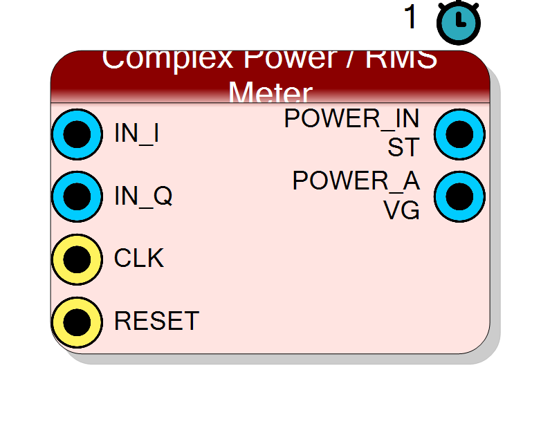
Measures the power of a complex I/Q stream: computes |A|^2 = I^2 + Q^2 and low-pass smooths it with a single-pole leaky integrator. Emits both the instantaneous power and a time-averaged power. Typical use: RSSI, AGC detector, squelch / signal-present decision.
Introduction
The Complex Power / RMS Meter computes the instantaneous power of the
complex input A = IN_I + j*IN_Q and then smooths it with a single-pole
IIR low-pass:
inst[n] = IN_I[n]^2 + IN_Q[n]^2 = |A[n]|^2
avg[n] = avg[n-1] + (inst[n] - avg[n-1]) >> SmoothShift
Both signals are brought out: POWER_INST is the raw sample-by-sample
power, POWER_AVG is the running smoothed power. The averaging pole gives
a stable RSSI / AGC reading that rejects the sample-rate ripple of the
squared envelope.
For an un-averaged power use Component_ComplexMagSq; for linear magnitude use Component_ComplexMagApprox or Component_ComplexAtan2.
Pin Description
I^2 + Q^2. Signed, 2*InputSize + 1 bits
(always >= 0).
Properties
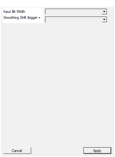
Bit width of each I/Q input (signed).
Bit width of each signed I / Q input sample. Range 4 to 32, default 16. SetsPOWER_INST = 2*InputSize + 1 and
POWER_AVG = 2*InputSize + 5.
Default: 16
Options: 4 5 6 7 8 9 10 11 12 13 14 15 16 17 18 19 20 21 22 23 24 25 26 27 28 29 30 31 32
Leaky IIR shift. Time constant ~= 2^SmoothShift samples. 0 = no smoothing.
Leaky-IIR shift controlling the averaging time constant (tau ~= 2^SmoothShift samples). Range 0 to 16, default 8
(~256-sample average). 0 disables smoothing so POWER_AVG tracks
POWER_INST. Bigger = slower and smoother.
Default: 8
Options: 0 1 2 3 4 5 6 7 8 9 10 11 12 13 14 15 16
Usage
Mathematical model
inst = I^2 + Q^2 (instantaneous |A|^2)
avg += (inst - avg) >> SmoothShift (single-pole leaky IIR)
The leaky integrator is a first-order low-pass with pole at
1 - 2^-SmoothShift. Its exponential time constant is approximately
tau ~= 2^SmoothShift samples
so SmoothShift = 8 averages over ~256 samples, SmoothShift = 0 disables
smoothing (avg tracks inst exactly). Larger shift = slower, smoother
reading with lower ripple but more lag.
Bit widths
Inputs are signed; both outputs are signed but always non-negative.
IN_I,IN_Q: signedInputSizebits.POWER_INST:2*InputSize + 1bits (full-precisionI^2 + Q^2).POWER_AVG:2*InputSize + 1 + 4bits= 2*InputSize + 5.
The averaged output carries 4 extra headroom bits (SMOOTH_HEADROOM)
above the instantaneous width. These guard bits absorb the accumulated
running-sum value inside the leaky integrator so the smoothed power does
not clip or lose low-order bits regardless of SmoothShift. With the
default InputSize = 16 the outputs are 33 and 37 bits.
Linear vs. dB
Both outputs are linear |A|^2. Feed them to an external log2
(or a log block) if a dB scale is required. Because power is |A|^2,
one octave of amplitude is 6 dB and the log slope is 10*log10 per
decade of the linear value.
Latency and throughput
#pragma HLS PIPELINE II=1: one sample pair per clock.- 1-clock latency on
POWER_INST;POWER_AVGis a recursive accumulator updated every clock (its value settles over ~2^SmoothShiftsamples). avgis astaticstate register;RESETclears it.- All ports use the
ap_noneinterface (no ready/valid handshake).
Reset
RESET is the HLS synchronous reset (ap_rst) and clears the internal
avg accumulator to zero, so the smoothed reading re-converges from 0
after a reset.
Typical applications
- RSSI :
POWER_AVGgives a stable received-signal-strength value. - AGC detector : compare
POWER_AVGagainst a set-point to drive a gain loop (see Component_ComplexAGC / Component_RealAGC). - Squelch / signal-present : threshold
POWER_AVG. - Pulse energy / peak power : read
POWER_INSTfor per-sample power.
Resources & Timing
-
Latency: 1 clock cycle (POWER_INST); POWER_AVG settles over ~2^SmoothShift samples
-
Throughput: 1 sample per clock (II=1)
Two DSP48 multipliers for I^2 and Q^2, one adder for the instantaneous power, and a single-pole leaky integrator (subtract + arithmetic shift + accumulate) for the average. No square root, no divider. The averaging accumulator has 4 guard bits above the instantaneous width.