
Serializer (Parallel to Serial)
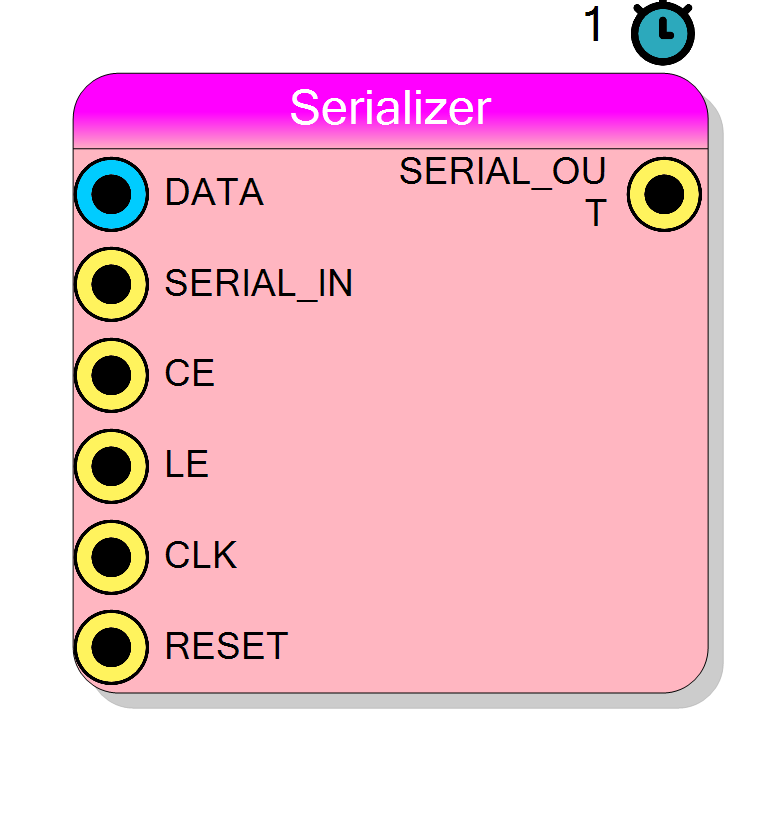
Converts parallel data to serial bit stream. Loads parallel DATA when LE=1, then shifts out bits one per clock cycle while CE=1. Supports MSB-first or LSB-first bit order. Can concatenate additional serial data via SERIAL_IN input.
Introduction
This block converts parallel data to serial by loading a parallel word and shifting it out one bit per clock cycle. Useful for interfacing with serial communication protocols.
Pin Description
Properties
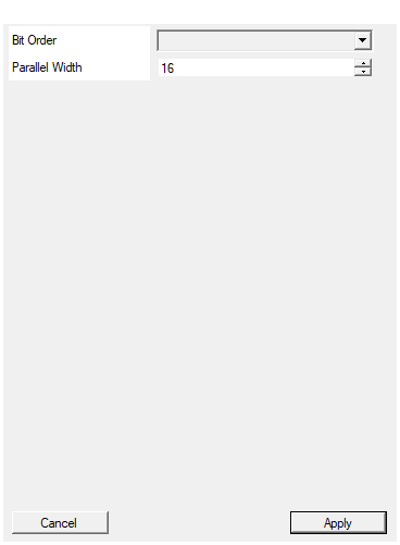
Set the order of the serialized bit
Bit transmission order: MSB FIRST or LSB FIRST.Default: MSB FIRST
Options: MSB FIRST LSB FIRST
Set the size in bits of the input parallel word width
Parallel word width. Range: 2-65535 bits.Default: 16
Range: 2 – 65535
Functional description
Operation sequence:
- Assert LE=1 to load parallel DATA
- Keep CE=1 while shifting out bits on SERIAL_OUT
- Optionally provide additional bits via SERIAL_IN after parallel data finishes
Bit order
- MSB FIRST: Most significant bit transmitted first
- LSB FIRST: Least significant bit transmitted first
Timing
Latency: 1 clock cycle to first bit output. Shift rate: 1 bit per clock cycle.
Typical use cases
- Serial communication interfaces (SPI, UART)
- Bit-serial arithmetic
- Data width conversion