

State Machine Examples
The eight ready-made state machines of the examples gallery (toggle, sequence detector, handshake, traffic light, acquisition controller, debouncer, timed pulse with a Timer and STATE ENTERED, capture and hold with State Variables): what each one does and which feature of the editor it shows.
The Examples Gallery
The gallery creates a new, complete machine - states, transitions, State Ports, State Variables and fully wired bodies - from one of eight templates. Open it from:
- the New State Machine from template… button of the project tree toolbar;
- Add State Machine from Example… in the context menu of the Unused folder or of the top node;
- the Examples… button in the header of the state machine editor;
- From example… in the Add State Machine dialog used to place a machine.
Select an example in the list: the right side shows a preview of its graph (the reset
state has a green border, labels are name [priority]) and a text with the purpose,
the inputs and outputs, the outputs of each state and the transitions in priority
order. Edit the name in New state machine name and click Create. An existing
machine is never modified.
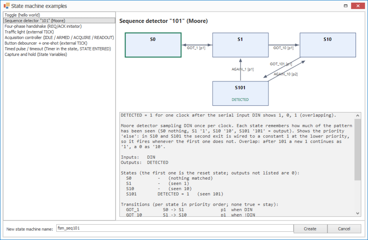
Figure 1: the examples gallery
The bodies are built with the same blocks you find in the palette: State Ports, Logic And / Or / Not, Bit Constant / Const Bit-Vector, EXIT CONDITION, STATE ACTIVE / STATE ENTERED, a Timer (Enable) and State Variable blocks. Every example has been verified by simulation of the generated VHDL. They are starting points: rename, extend and re-wire them freely.
1. Toggle (hello world)
Two states, LED on/off: each clock with EN = 1 flips the state.
States OFF (reset) and ON; transitions TURN_ON (OFF → ON) and TURN_OFF (ON →
OFF), both conditioned by EN. LED = 1 only in ON. Holding EN at 1 toggles on every
clock: drive EN with a one-clock pulse (for example the PULSE of the Debouncer example)
to toggle once per button press.
Shows: the smallest machine, an output driven in only one state (0 elsewhere).
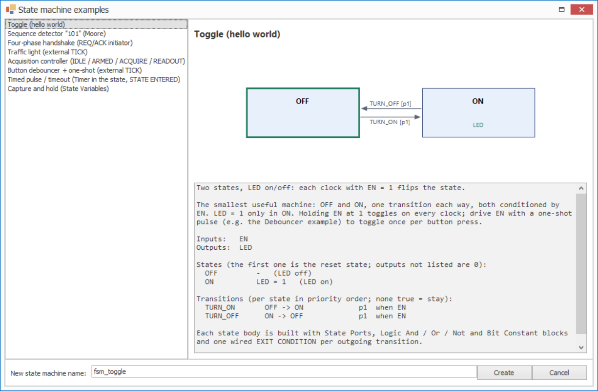
Figure 2: Toggle
2. Sequence detector “101” (Moore)
DETECTED = 1 for one clock after the serial input DIN shows 1, 0, 1 (overlapping).
States S0, S1, S10, S101 remember how much of the pattern has been seen;
DETECTED = 1 in S101. In S10 and S101 the second exit (RESTART, AGAIN_10) is
wired to a constant 1 at priority 2: it fires whenever the priority-1 exit does not.
Shows: priority as “else” - no NOT gate is needed.
3. Four-phase handshake (REQ/ACK initiator)
START raises REQ, waits ACK, drops REQ, waits ACK low, pulses DONE.
States IDLE, REQUEST (REQ = 1, BUSY = 1), RELEASE (BUSY = 1), FINISH (DONE = 1).
FINISH leaves unconditionally (constant 1), so DONE is a one-clock pulse. ACK coming
from another clock domain must be synchronized before reaching the machine.
Shows: return-to-zero protocol, unconditional exit for a one-clock state.
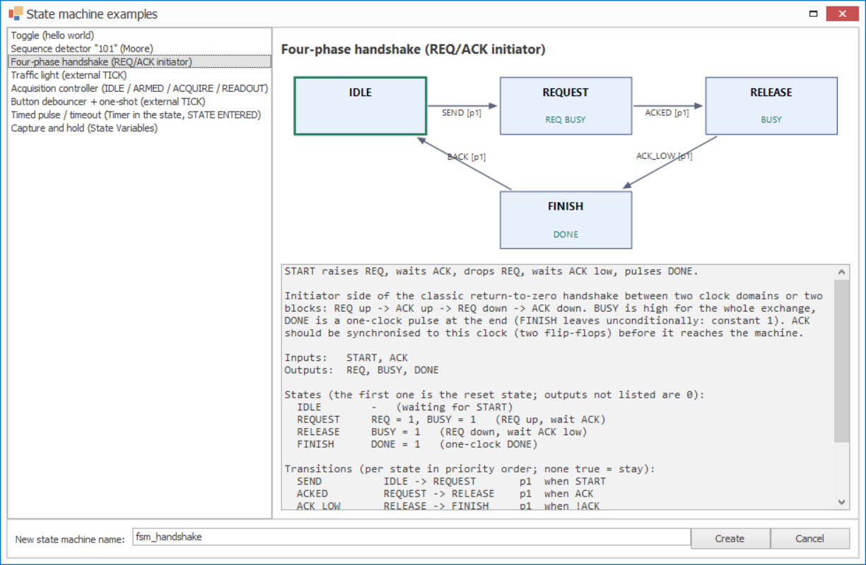
Figure 3: Four-phase handshake
4. Traffic light (external TICK)
STOP → GO → CAUTION → STOP, one step per TICK pulse; drives RED / GREEN / YELLOW.
TICK is a one-clock strobe produced on the parent page (for example by a prescaler at
1 Hz). Each state lights one lamp and advances on TICK.
Shows: time base from outside the machine. For a different duration per colour, place a timer in each body (see example 7).
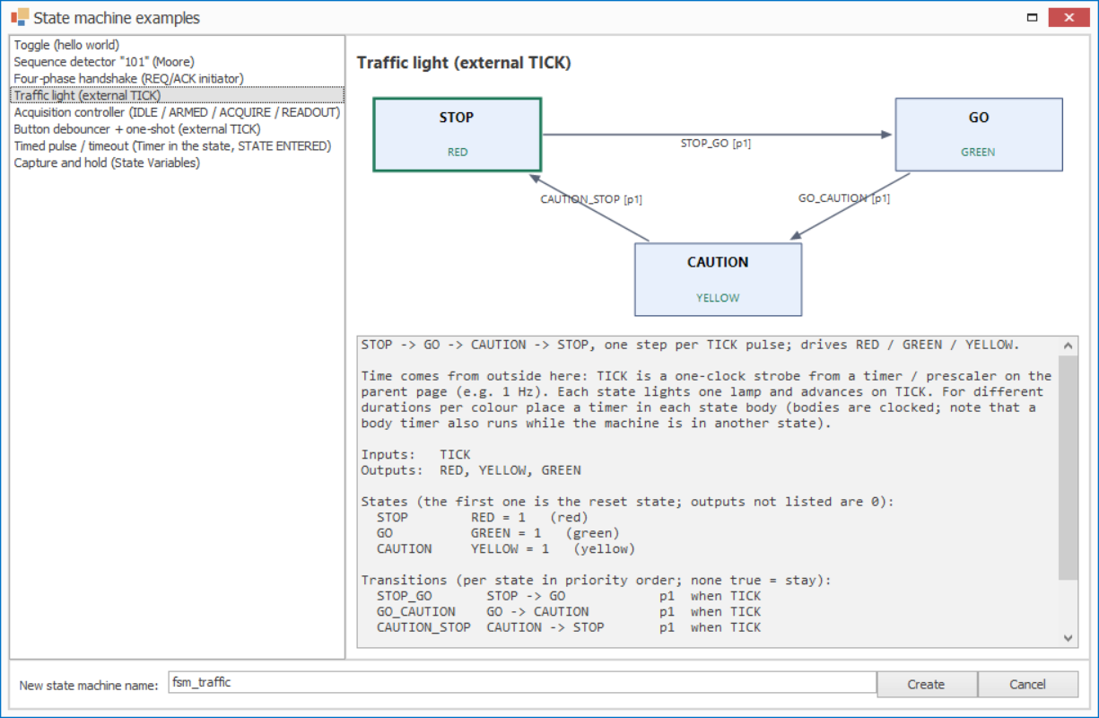
Figure 4: Traffic light
5. Acquisition controller (IDLE / ARMED / ACQUIRE / READOUT)
ARM → wait TRIGGER → acquire until GATE_END → readout until READ_DONE; ABORT wins.
BUSY = 1 in every state but IDLE, ACQ_EN = 1 in ACQUIRE, DATA_READY = 1 in
READOUT. ARMED and ACQUIRE have two exits each: the ABORT exits (ARMED_ABORT,
ACQ_ABORT) have priority 1, so ABORT together with TRIGGER or GATE_END goes back to
IDLE.
Shows: priority between two real conditions, typical run control of a triggered acquisition.
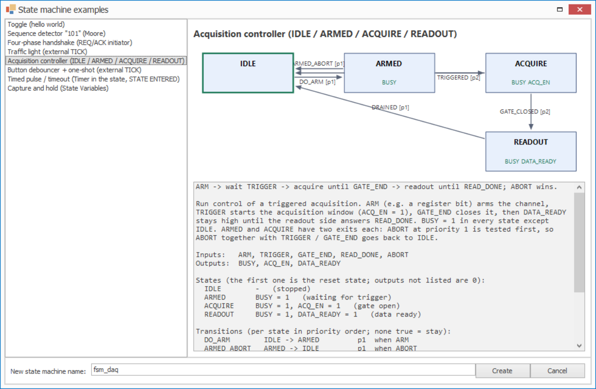
Figure 5: Acquisition controller
6. Button debouncer + one-shot (external TICK)
BTN must be stable on two TICKs to change LEVEL; PULSE = one clock per confirmed press.
States UP, PRESSING, FIRE, DOWN, RELEASING. A press is confirmed when BTN is
still 1 on the next TICK (PRESSING → FIRE); a bounce goes back (BOUNCE_UP,
BOUNCE_DOWN). FIRE lasts one clock and gives PULSE; LEVEL is the debounced
button. TICK is a slow sampling strobe (e.g. 1 kHz) from the parent page.
Shows: a five-state protocol, a one-clock state used as a one-shot.
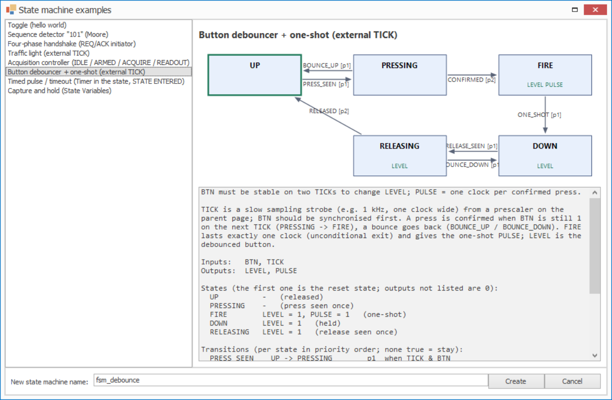
Figure 6: Button debouncer
7. Timed pulse / timeout (Timer in the state, STATE ENTERED)
START → PULSE high for a fixed time counted by a Timer block inside the ACTIVE state; START again restarts it.
The ACTIVE body contains a Timer (Enable) named TMR: STATE ENTERED resets it, STATE
ACTIVE enables it, TARGET comes from a Const Bit-Vector (default 4, 16 bit). Exits:
RETRIGGER (self-loop, priority 1) = START AND NOT STATE ENTERED, TIMEOUT (back to
IDLE, priority 2) = TMR.EXPIRED AND NOT STATE ENTERED. PULSE lasts N + 4 clocks
(entry clock, the Timer’s registered ENABLE, N counts, the EXPIRED clock).
Shows: a clocked block in a body, the restart-on-entry idiom, self-loop re-entry
(STATE ENTERED pulses again), and why exits read counters AND NOT STATE ENTERED. With
this Timer, whose reset is asynchronous, the qualifier is redundant; it is required
with synchronously cleared counters, so keep the habit.
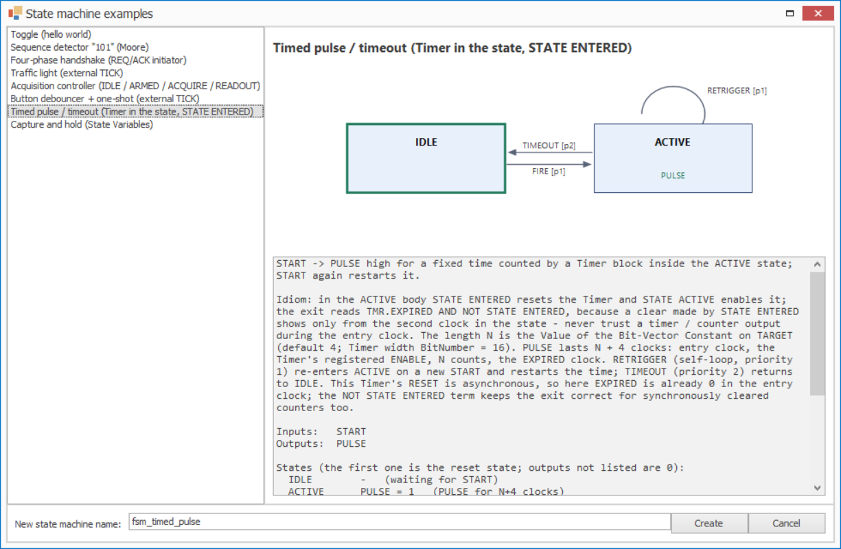
Figure 7: Timed pulse in the gallery
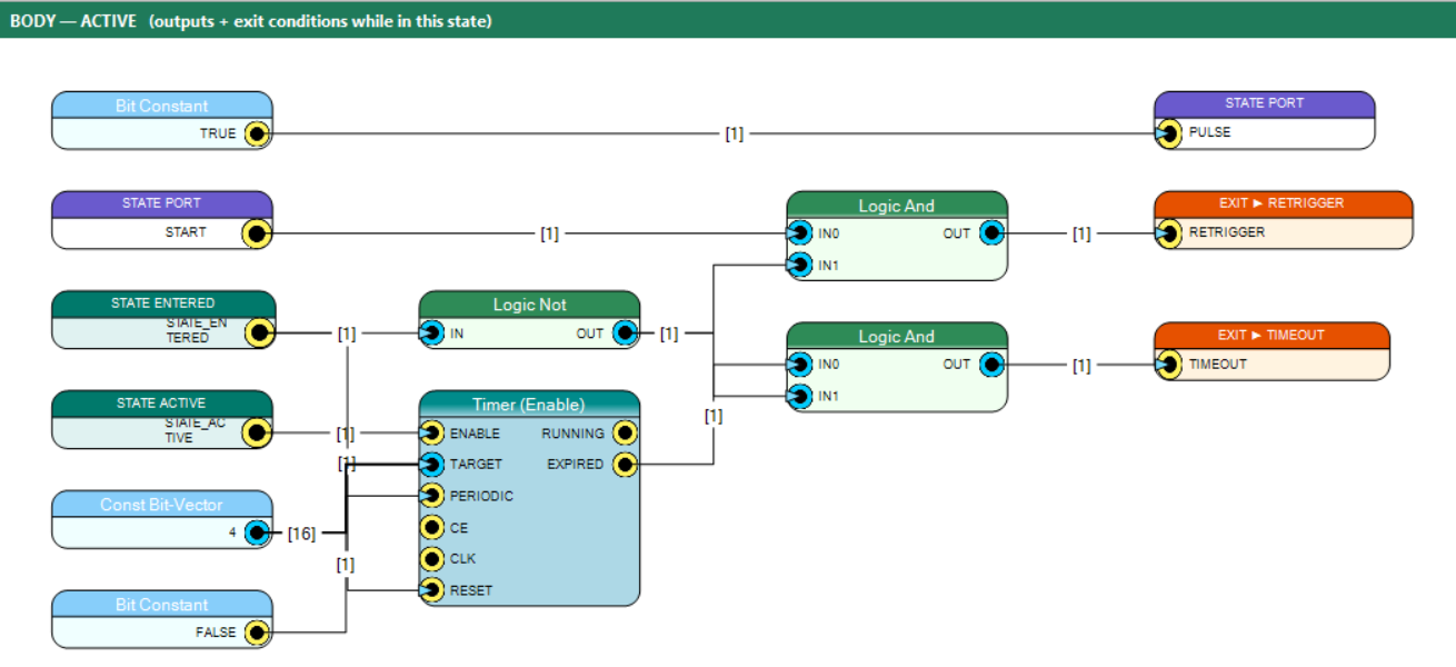
Figure 8: body of state ACTIVE: STATE ENTERED / STATE ACTIVE drive the Timer, the two EXIT CONDITIONs are qualified by NOT STATE ENTERED, PULSE is driven by a constant 1
8. Capture and hold (State Variables)
TRIGGER → CAPTURE stores the 8-bit DATA_IN in the State Variable LATCHED; HOLD shows it (VALID) until ACK.
Ports: in TRIGGER, ACK, DATA_IN (8 bit); out DATA_OUT (8 bit), VALID, DONE.
State Variables: LATCHED (8 bit, reset 0) and ACKED (1 bit, reset 0).
IDLE --TAKE (TRIGGER)--> CAPTURE --STORED (1)--> HOLD --RELEASE (ACK)--> IDLE.- CAPTURE (one clock) writes DATA_IN into LATCHED and 0 into ACKED, both with WRITE unconnected (= every clock in the state).
- HOLD writes 1 into ACKED with WRITE = ACK (the clock that leaves HOLD).
- Every state drives DATA_OUT = LATCHED and DONE = ACKED; VALID = 1 in HOLD.
Shows: a value captured in one state and used in another, the next-state timing (CAPTURE still shows the old value, HOLD the new one), a value kept where nothing writes it, several states writing one variable, a WRITE enable, RESET loading the reset value.
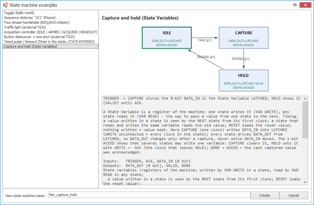
Figure 9: Capture and hold in the gallery
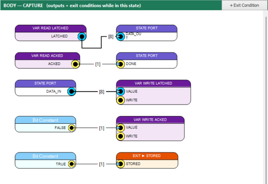
Figure 10: body of state CAPTURE: VAR WRITE LATCHED from DATA_IN, VAR WRITE ACKED from FALSE, both written every clock (WRITE unconnected), EXIT ► STORED unconditional