
Zero Fill [TM]
Time-multiplexed bit extension operation that increases bit width by padding with zeros. Extends unsigned binary numbers to wider formats while preserving value. Supports configurable alignment (left or right) and TM factors from 2 to 32. Pure combinational logic (zero latency).
Introduction
This block performs zero-fill bit extension on time-multiplexed (TM) data streams. It extends the input word to a wider output format by appending zeros, preserving the unsigned value of the input.
The operation is purely combinational with zero latency. Zeros can be added to either:
- MSB side (RIGHT alignment - standard zero extension)
- LSB side (LEFT alignment - left shift equivalent)
This block is used for unsigned numbers only. For signed numbers, use Sign Extend instead.
The TM Factor property determines how many parallel samples are processed per clock cycle.
Pin Description
Input Width × TM Factor
Output Size × TM Factor
Output is combinational (zero latency).
Properties
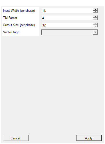
Set the input word size in bits per phase
Number of bits per input sample. Range: 2 – 128. Must be ≤ Output Size.Default: 16
Range: 2 – 128
Set the time multiplexing factor (number of phases)
Time-multiplexing factor (number of parallel phases). Allowed values: 2, 4, 8, 16, 32.Default: 4
Range: 2 – 32
Set the output word size in bits per phase
Number of bits per output sample. Range: 0 – 128. Must be ≥ Input Width. Number of zeros added = Output Size - Input Width.Default: 32
Range: 0 – 128
Select if output should be aligned on right (Zeros fill the MSBs) or LEFT
Alignment mode:
- RIGHT: Input in LSBs, zeros in MSBs (standard unsigned extension)
- LEFT: Input in MSBs, zeros in LSBs (left shift)
Default: RIGHT
Options: RIGHT LEFT
Functional description
The component implements zero-fill extension in VHDL, replicated N times (where N = TM Factor) to support time-multiplexed data streams.
For each TM phase:
- Input width = Input Width bits
- Output width = Output Size bits (must be ≥ Input Width)
- Padding = Output Size - Input Width zero bits
Alignment modes
-
RIGHT alignment (default):
- Input is placed in the LSBs (rightmost bits)
- Zeros fill the MSBs (leftmost bits)
- Standard zero extension for unsigned numbers
- Example: 8-bit
11010110→ 16-bit00000000 11010110
-
LEFT alignment:
- Input is placed in the MSBs (leftmost bits)
- Zeros fill the LSBs (rightmost bits)
- Equivalent to left shift by (Output Size - Input Width)
- Example: 8-bit
11010110→ 16-bit11010110 00000000
Mathematical background
- RIGHT alignment: Preserves unsigned value: $y = x$
- LEFT alignment: Multiplies by $2^{(W_{\text{out}} - W_{\text{in}})}$: $y = x \times 2^{\Delta W}$
Common uses:
- Unsigned number format conversion (8-bit to 16-bit, etc.)
- Fixed-point fractional width adjustment
- Bit field packing and alignment
- ADC/DAC data format conversion
Timing
The component is purely combinational with zero latency:
| Property | Latency (clock cycles) |
|---|---|
| Zero Fill TM | 0 |
All TM phases are processed in parallel within the same clock cycle.
Typical use cases
- Unsigned integer width conversion (8→16, 16→32 bits)
- Fixed-point fractional part zero-padding
- Memory/register width adaptation
- Communication protocol format conversion
- ADC sample width extension