
Both Edge Detector
Dual-edge detector that generates single-cycle pulses when input signals transition in either direction (rising or falling). Creates configurable-width pulses for each detected edge on multi-bit input vectors. Supports independent edge detection on each bit with programmable pulse width. Essential for toggle detection, change monitoring, and event counting regardless of transition direction.
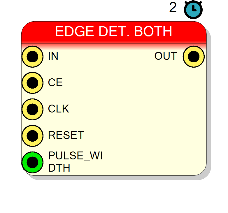
Introduction
This block implements a both-edge detector that generates output pulses whenever an input signal transitions in either direction: ‘0’→‘1’ (rising) OR ‘1’→‘0’ (falling).
The edge detector operates as follows:
- Monitors input signal(s) for any transition (0→1 or 1→0)
- Generates a pulse on OUT for each detected edge
- Pulse width is configurable (default: 1 clock cycle)
- Each bit in multi-bit inputs has an independent edge detector
Key characteristics:
- Dual-edge triggered: Responds to both rising and falling edges
- Toggle detection: Detects any change in signal state
- Multi-bit: Processes up to 128 independent signals
- Pulse generation: Creates clean, synchronous pulses
- Configurable width: Pulse duration from 1 to N clock cycles
- Latency: 2 clock cycles
Pin Description
Clock Enable input (active high).
- CE = ‘1’: Edge detection enabled
- CE = ‘0’: Edge detection disabled (input changes ignored) Default: ‘1’ if left unconnected.
Pulse width in clock cycles (integer). Determines how many cycles the output pulse remains high after edge detection.
- PULSE_WIDTH = 1: Single-cycle pulse
- PULSE_WIDTH = N: N-cycle pulse Default: 1 if left unconnected.
Properties
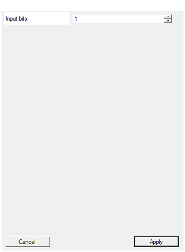
Set the number of bits of the input signal. For each bit will be created an indipendent edge detector
Number of independent edge detectors (width of IN and OUT). Range: 1-128 bits. Each bit detects both rising and falling edges independently.Default: 1
Range: 1 – 128
Functional description
A both-edge detector identifies any transition on input signals and generates synchronized output pulses. Each bit of the input has its own independent edge detection circuit.
Operation principle
For each input bit $i$:
$$ \mathrm{Edge}[i] = \mathrm{IN}i \oplus \mathrm{IN}i $$
Where:
- $\mathrm{IN}i$ = current value of bit $i$
- $\mathrm{IN}i$ = previous value of bit $i$ (1 clock ago)
- $\oplus$ = logical XOR (exclusive OR)
An edge is detected when:
- 0→1 transition (rising edge), OR
- 1→0 transition (falling edge)
In other words, any change in the signal state triggers detection.
Pulse generation
When any edge is detected:
- Output bit goes HIGH for PULSE_WIDTH clock cycles
- After PULSE_WIDTH cycles, output returns to LOW
- New edges can be detected after the pulse completes
Multi-bit operation
The component processes each input bit independently:
- Input Size = 8 → 8 independent edge detectors
- Each detector operates on its corresponding bit
- Edges on different bits are detected simultaneously
- OUT[i] reflects edge detection for IN[i]
Pulse width control
The PULSE_WIDTH input (integer) determines pulse duration:
- PULSE_WIDTH = 1: Single-cycle pulse (default)
- PULSE_WIDTH = N: N-cycle pulse
Timing
| Property | Latency (clock cycles) |
|---|---|
| Both Edge Detector | 2 |
The output pulse appears 2 clock cycles after an edge occurs on the input.
Timing diagram
Cycle: 0 1 2 3 4 5 6 7
CLK: ↑ ↑ ↑ ↑ ↑ ↑ ↑ ↑
IN: 0 1 1 0 1 1 0 0
OUT: 0 0 1 0 1 0 1 0
(↑) (pulse)(↓)(pulse)(↑)(pulse)(↓)
Both rising (↑) and falling (↓) edges generate pulses.
Edge Detector Comparison
Both Edge Detector (this component):
- Detects 0→1 AND 1→0 transitions
- Use for toggle/change detection
- Counts all transitions
Rising Edge Detector:
- Detects only 0→1 transitions
- Use for activation events
Falling Edge Detector:
- Detects only 1→0 transitions
- Use for deactivation events
Typical use cases
- Toggle detection: Detect button toggles regardless of direction
- Change monitoring: Monitor when signals change state
- Frequency measurement: Count transitions for frequency calculation
- Event counting: Count all state changes (rising + falling)
- Activity detection: Detect any activity on control signals
- Clock edge counting: Count both clock edges for DDR systems
- Protocol monitoring: Detect all signal transitions in communication
- Glitch detection: Identify unexpected signal changes
Design best practices
- High sensitivity: Detects all transitions - ensure input is stable
- Glitch filtering: May need debouncing for mechanical inputs
- Metastability: Synchronize async inputs before detection
- Double counting: Each toggle generates one pulse (not two)
- Pulse spacing: Ensure PULSE_WIDTH doesn’t overlap with next edge
Waveform example
Example with Input Size = 2, PULSE_WIDTH = 1:
Note: Every transition (↑ and ↓) generates a pulse after 2-cycle latency.