
List
Simple FIFO-based data transfer block with configurable word size. Unlike Custom Packet, this is a raw FIFO that transfers fixed-size words directly to the PC without packet structure or headers.
Introduction
Principle of Operation
The List block implements a simple FIFO (First-In-First-Out) buffer for transferring raw data words from FPGA to PC. Each word written to the FIFO is transferred to the PC as a continuous byte stream.
List vs Custom Packet
Both List and Custom Packet are FIFO-based transfer mechanisms, but they serve different purposes:
| Feature | List | Custom Packet |
|---|---|---|
| Data structure | Raw words (no header) | Structured packets with header |
| Word size | Fixed (32-8192 bits) | 32-bit rows with custom layout |
| Packet format | None - just raw data | User-defined with constants, timecode, etc. |
| Use case | Simple data streaming | Complex event structures |
| Overhead | Minimal | Header overhead per packet |
| Analogy | Raw array transfer | C struct transfer |
When to use List:
- Streaming simple values (counters, ADC samples, timestamps)
- High-throughput raw data transfer
- When data interpretation is done on the PC side
- Minimal protocol overhead needed
When to use Custom Packet:
- Complex event structures with multiple fields
- Need for packet synchronization (header constants)
- Event-based acquisition with timestamps and metadata
- Self-describing data format
The List block data can be read via Resource Explorer or programmatically using the SciSDK library.
SciSDK Documentation: https://nuclearinstruments.github.io/SCISDK/
Pin Description
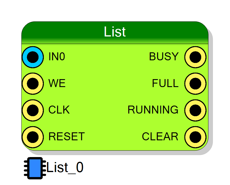
Busy – HIGH when the block is not accepting data.
This signal is HIGH when:
- Acquisition is disabled (
CONFIG[0] = 0), OR - FIFO is full
Logic: BUSY = NOT CONFIG[0] OR FULL
Use this signal to gate your data source when the List cannot accept more data.
Running – HIGH when acquisition is enabled via software.
Logic: RUNNING = CONFIG[0]
This signal directly mirrors the enable bit of the CONFIG register.
Clear – Outputs the internal reset signal.
Logic: CLEAR = CONFIG[1] OR RESET
Goes HIGH when either:
- Software reset is requested (
CONFIG[1] = 1), OR - Hardware RESET input is asserted
Use this signal to reset upstream logic when the List FIFO is cleared.
Data Input – Input data word to be written to the FIFO. Size is configurable (32 to 8192 bits).
Data is captured on the clock edge when WR is HIGH.
Write Enable – When HIGH (and acquisition is enabled), the value on IN is written to the FIFO on the clock edge.
If FIFO is full, data is lost.
Properties
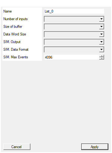
Set the name of the endpoint
Logical endpoint name used in register map. Used in Resource Explorer and SciSDK. Default: List_0Default: List_0
Set the number of input to the virtual block
Default: 1
Options: 1 2 4 8 16 32 64 128
Size of the readout buffer. Buffer must be large enought to compensate readout bus stalls.
FIFO buffer depth in words. Available values: 128, 256, 512, 1024, 2048, 4096, 8192, 16384, 32768, 65536.
Larger buffers compensate for readout bus stalls but use more FPGA resources. Default: 1024
Default: 1024
Options: 128 256 512 1024 2048 4096 8192 16384 32768 65536
Set the data word size in bits
Input data word size in bits. Available values: 32, 64, 128, 256, 512, 1024, 2048, 4096, 8192.
Larger words are converted to multiple 32-bit transfers internally. Default: 32
Default: 32
Options: 32 64 128 256 512 1024 2048 4096 8192
What the block writes to disk WHEN THE PROJECT IS SIMULATED (no effect on the synthesized design). None: the block does nothing, as it has always done. Single file: every word pushed into the list goes into one file, channel 0 first. Multi file per channel: one file per input. The files are written in the sim_results folder of the project, named after
What the block writes to disk when the project is simulated. It has no effect on the synthesized design.
| Value | Effect |
|---|---|
| None | Nothing is written (default). |
| Single file | Every word pushed into the list goes into one file, channel 0 first. |
| Multi file per channel | One file per input. |
Files go to the project’s sim_results folder, named after <page>_<endpoint> plus
_ch<n> in the multi-file mode. The exact paths are printed in the compiler log.
In a simulation nobody starts the list and nobody reads it out, so the block
starts itself and is drained as fast as it fills: FULL stays low and no
word is lost. There is no per event mode, because a list event is a single write —
one file per event would mean one file per word.
Default: None
Default: None
Options: None Single file Multi file per channel
How the words are written. Binary - little endian (default): a raw byte stream, ceil(WordSize/8) bytes per word, least significant byte first. No header, no timestamp: feed it straight to a decoder. Extension .bin Binary - big endian: the same, most significant byte first. Hex text: one row per write, ‘<time_ns>
How the words are written.
| Value | File | Content |
|---|---|---|
| Binary - little endian | .bin |
Raw byte stream, ceil(WordSize/8) bytes per word, least significant byte first. |
| Binary - big endian | .bin |
The same, most significant byte first. |
| Hex text | .txt |
One row per write: <time_ns> <W0> <W1> …, each word as WordSize/4 hex digits, most significant first. |
The binary formats are a bare stream — no header, no timestamp, no padding — so
the file can be fed straight to a decoder. X/U bits are written as 0. The hex
format is text, carries a header describing the columns and the ns timestamp of every
write, and marks a nibble holding X/U as X rather than silently zeroing it.
Default: Binary - little endian
Default: Binary - little endian
Options: Binary - little endian Binary - big endian Hex text
Stop capturing after this many writes. The list free-runs in simulation, so this is what keeps a long run from filling the disk - one write costs Channels * WordSize/8 bytes. 0 means no limit.
Stop capturing after this many writes. The list free-runs in simulation, so this is what keeps a long run from filling the disk — one write costsChannels × WordSize/8 bytes. 0 means no limit.
Default: 4096
Default: 4096
⚙️ Detailed Operation
Data Flow
┌──────────────────────────────────────────────────────────────────┐
│ List Data Flow │
│ │
│ IN (32-8192 bits) ──►┌──────────┐ ┌─────────────┐ │
│ │ │ │ │ │
│ WR ─────────────────►│ FIFO │────►│ Raw Data │───► PC │
│ │ Buffer │ │ Stream │ │
│ CLK ────────────────►│ │ │ │ │
│ RESET ──────────────►└──────────┘ └─────────────┘ │
│ │ │
│ ┌────┴────┐ │
│ │ FULL │──► HIGH when buffer full │
│ │ BUSY │──► HIGH when not accepting │
│ │ RUNNING │──► HIGH when enabled │
│ │ CLEAR │──► Outputs reset signal │
│ └─────────┘ │
└──────────────────────────────────────────────────────────────────┘
Write Operation
- Acquisition must be started via software (CONFIG register bit 0 = 1)
- When WR goes HIGH, the value on IN is written to the FIFO
- Data is transferred to PC as a continuous stream
- FULL goes HIGH if the FIFO overflows (data loss!)
Signal Timing
The internal write signal is generated by the following logic:
iWRITE = CONFIG[0] AND WR AND (NOT FULL)
This means data is written to the FIFO only when all three conditions are true:
- Acquisition is enabled (
CONFIG[0] = 1) - Write request is active (
WR = 1) - FIFO is not full (
FULL = 0)
Output signals logic:
| Signal | Logic | Description |
|---|---|---|
RUNNING |
CONFIG[0] |
Mirrors the enable bit |
BUSY |
NOT CONFIG[0] OR FULL |
HIGH when stopped OR full |
FULL |
Internal FIFO full flag | HIGH when buffer overflows |
CLEAR |
CONFIG[1] OR RESET |
Outputs internal reset |
Important: The BUSY signal is HIGH when acquisition is disabled (stopped state),
which indicates that the block is not accepting new data. It also goes HIGH when the FIFO is full.
Timing Diagrams
Normal Write Sequence:
FIFO Full Condition:
Reset Sequence:
Start/Stop Acquisition:
Word Size and Conversion
The input word size is configurable from 32 to 8192 bits. Internally, words are converted to 32-bit chunks for transfer:
| Input Size | 32-bit Words per Sample |
|---|---|
| 32 bits | 1 |
| 64 bits | 2 |
| 128 bits | 4 |
| 256 bits | 8 |
| … | … |
| 8192 bits | 256 |
Important: All transfers are done with a size multiple of the FPGA word size to prevent partial word corruption.
Data Interpretation
Since List transfers raw data without headers, the user must know the data format and cast the raw bytes appropriately. For complex multi-field data, use packed structures:
c
// Example: 64-bit word with multiple fields
#pragma pack(push, 1)
typedef struct {
uint16_t channel : 5;
uint16_t valid : 1;
uint16_t pileup : 1;
uint32_t timestamp : 24;
uint16_t energy : 16;
uint16_t reserved : 17;
} MY_DATA_STRUCT; // Total: 64 bits
#pragma pack(pop)
Configuration Registers
CONFIG
| Bit | Function |
|---|---|
| 0 | Enable acquisition (1 = running, 0 = stopped) |
| 1 | Force reset |
STATUS
| Bit | Function |
|---|---|
| 0 | Empty (1 = FIFO empty) |
| 1 | Full (1 = FIFO full) |
Software Integration with SciSDK
The List is fully supported by SciSDK. For complete documentation see: SciSDK List Guide
Available Parameters
| Parameter | Access | Description | Default |
|---|---|---|---|
acq_len |
R/W | Maximum samples per FIFO read | 1024 |
acq_mode |
R/W | blocking or non-blocking |
blocking |
timeout |
R/W | Timeout in ms for blocking mode | 100 |
thread |
R/W | Enable internal threading for high performance | false |
high_performance |
R/W | Priority bus access mode | false |
threaded_buffer_size |
R/W | Internal buffer size in dwords | 100000 |
Available Commands
| Command | Description |
|---|---|
start |
Clear FIFO and begin acquisition |
stop |
Stop acquisition |
Buffer Structure
c
typedef struct {
uint32_t magic; // Buffer type identifier
char *data; // Raw data array (cast to appropriate type)
struct {
uint32_t buffer_size;
uint32_t samples;
uint32_t valid_samples;
uint32_t channels;
} info;
} SCISDK_LIST_RAW_BUFFER;
C/C++ Example
c
#include "SciSDK_DLL.h"
// Define data structure matching FPGA word
#pragma pack(push, 1)
typedef struct {
uint32_t timestamp;
uint16_t energy;
uint16_t channel;
} EVENT_DATA; // 64 bits
#pragma pack(pop)
// Allocate buffer (1024 samples)
SCISDK_LIST_RAW_BUFFER *buffer;
SCISDK_AllocateBufferSize("board0:/MMCComponents/List_0",
T_BUFFER_TYPE_RAW,
(void**)&buffer, _sdk, 1024);
// Configure
SCISDK_SetParameterString("board0:/MMCComponents/List_0.acq_mode",
"blocking", _sdk);
SCISDK_SetParameterInteger("board0:/MMCComponents/List_0.timeout",
1000, _sdk);
// Start acquisition
SCISDK_ExecuteCommand("board0:/MMCComponents/List_0.start", "", _sdk);
// Read data
while (running) {
int ret = SCISDK_ReadData("board0:/MMCComponents/List_0",
(void*)buffer, _sdk);
if (ret == NI_OK && buffer->info.valid_samples > 0) {
// Cast raw data to our structure
EVENT_DATA *events = (EVENT_DATA*)buffer->data;
for (int i = 0; i < buffer->info.valid_samples; i++) {
printf("Event %d: ch=%d, energy=%d, ts=%u\n",
i, events[i].channel, events[i].energy,
events[i].timestamp);
}
}
}
// Stop and free
SCISDK_ExecuteCommand("board0:/MMCComponents/List_0.stop", "", _sdk);
SCISDK_FreeBuffer("board0:/MMCComponents/List_0",
T_BUFFER_TYPE_RAW, (void**)&buffer, _sdk);
Python Example
python
from scisdk.scisdk import SciSDK
import struct
sdk = SciSDK()
sdk.AddNewDevice("usb:10500", "dt5560", "board0", "RegisterFile.json")
# Allocate buffer
res, buf = sdk.AllocateBufferSize("board0:/MMCComponents/List_0",
sdk.T_BUFFER_TYPE_RAW, 1024)
# Configure
sdk.SetParameter("board0:/MMCComponents/List_0.acq_mode", "blocking")
sdk.SetParameter("board0:/MMCComponents/List_0.timeout", 1000)
# Start and read
sdk.ExecuteCommand("board0:/MMCComponents/List_0.start", "")
res, buf = sdk.ReadData("board0:/MMCComponents/List_0", buf)
if res == 0 and buf.info.valid_samples > 0:
# Interpret raw data (example: 64-bit words)
word_size = 8 # bytes per word
for i in range(buf.info.valid_samples):
offset = i * word_size
# Unpack as little-endian: timestamp(32), energy(16), channel(16)
ts, energy, ch = struct.unpack('<IHH', buf.data[offset:offset+word_size])
print(f"Event {i}: ch={ch}, energy={energy}, timestamp={ts}")
sdk.ExecuteCommand("board0:/MMCComponents/List_0.stop", "")
High Performance Mode
For high-rate applications, enable threaded mode:
c
SCISDK_SetParameterString("board0:/MMCComponents/List_0.thread", "true", _sdk);
SCISDK_SetParameterInteger("board0:/MMCComponents/List_0.threaded_buffer_size",
1000000, _sdk);
This creates an internal thread that continuously reads data into a large buffer, preventing data loss when user processing is slower than acquisition rate.
Resource Explorer
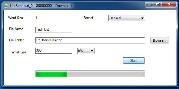
The List Module tool in Resource Explorer provides real-time data visualization and can save data to file.
Quick Reference
| Item | Description |
|---|---|
| Transfer unit | Raw words (no header/footer) |
| Word size | 32, 64, 128, … 8192 bits |
| PC transfer | 32-bit chunks |
| Data format | User-defined (raw bytes) |
| Best for | Simple streaming, high throughput |
Simulation Output
In the synthesized design the list is started by software writing CONFIG, and drained
by software reading the FIFO. During a project simulation neither happens, so the
block would sit disabled and show nothing. With SIM. Output set, it instead starts
itself, accepts every WE strobe, and writes the words straight to the project’s
sim_results folder.
Two consequences worth knowing:
- The FIFO is drained as fast as it fills. Modelling the real back-pressure would
mean losing every word after the first
BufferSizeones, since nothing reads the FIFO in a simulation — soFULLstays low and every accepted write reaches the file. RUNNINGandCLEARare now driven. The previous simulation model left them unconnected, so they sat at'U'and poisoned whatever they fed. With SIM. Output = None they are driven low instead.
Files are closed after every write, so the data on disk is complete even if the simulation is stopped in the middle of the run, and an unwritable path degrades to one warning instead of killing the simulation.
Only Xilinx targets have a simulation model for this block; on Intel targets the compiler now warns that the List will not simulate.
Resources & Timing
-
Latency: 1 clock cycle write latency
-
Throughput: One word per clock cycle (up to FIFO bandwidth)
- Uses BRAM for FIFO storage
- Raw data transfer without packet overhead
- Word size fixed at compile time
- User must interpret raw bytes on PC side
- Threaded mode available for high-rate applications
- Monitor FULL signal to prevent data loss