
Citiroc Frame Transfer - (V2)
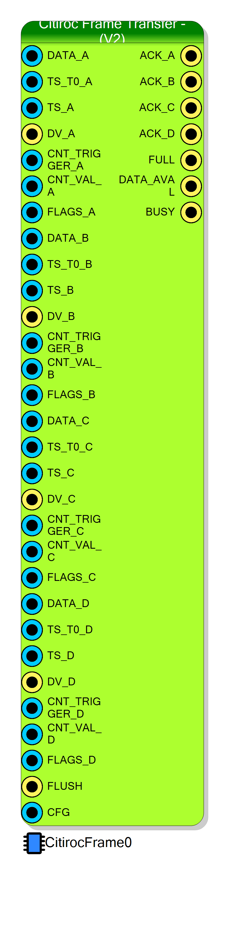
Event collector and PC readout endpoint for the four CITIROC 1A ASICs of the DT5550W-Citiroc1A-V2 board. Same round-robin arbiter and dual-clock FIFO as the V1 block, but the packet is three words longer: after the 32 channel words it appends the trigger counter, the validation counter and the FLAGS status word produced by the Citiroc Analog - TDC (V2) block, so every event carries its own trigger/validation bookkeeping to the host.
Introduction
Principle of Operation
This block does for the V2 board exactly what Citiroc Frame Transfer does for the V1
board: a state machine polls the four ASIC slots one per clock cycle, latches a complete
event in a single cycle when it finds an unmasked DV_x asserted, pulses ACK_x, and
then shifts the packet word by word into an xpm_fifo_async that the host drains
through a memory-mapped FIFO endpoint.
The difference is what goes into the packet. The Citiroc Analog - TDC (V2) block
exports three extra 32-bit words per event — how many triggers it has seen
(CNT_TRIGGER), how many validations it has seen (CNT_VAL) and why this particular
event was released (FLAGS). This block captures all three at latch time and inserts
them between the last channel word and the trailer, making the packet 41 words
instead of 38.
Those three words are what let the host account for every trigger: CNT_TRIGGER
advances on triggers the firmware accepted, Pack_Id advances on events this block
acknowledged, and the number of packets actually received is smaller than both by the
number lost to FIFO back-pressure. Comparing the three reconstructs the complete live
time and efficiency budget.
Pin Description
CONTROL[8]. While high it resets the
arbiter, clears the event counter and flushes the FIFO (and holds BUSY high, since
BUSY resets to 1 in this version). If left unconnected the compiler ties it to
the board’s FIFO_RESET net.
VALIDATION_REG), but not used by the HDL of this block. It has no effect here;
the register that matters is the CFG pin of the Citiroc Analog - TDC (V2) block.
prog_full flag, asserted 76 words (two packets)
before the real full. While it is high, incoming events are acknowledged but
discarded. Use it to throttle the trigger.
prog_empty flag, so it rises only when at
least 76 words (two complete packets) are buffered. Same bit the host reads as
STATUS[0].
1, unlike V1).
P_FRAME_DATA pin of the matching Citiroc Analog -
TDC (V2) block. 32 channel words of 32 bits, channel 0 in the most significant word.
Copied verbatim into words 5…36 of the packet, serialised LSW-first — so packet
word 5 is ASIC channel 31.
TS0_OUT. Becomes word 1.
TS_OUT — on V2 this is the
TDC-refined value whose four LSBs are the fine time inside one clock period. Split
into words 2 (low) and 3 (high). It is safe to take it from TS_OUT directly
because this block latches it only when DV_x rises, after the TDC has written it.
P_FRAME_DV. Sampled when
the arbiter reaches that ASIC’s slot; must stay high until the matching ACK is
returned. Masked ASICs (CONTROL[0..3] = 1) are never sampled.
CNT_TRIGGER, sampled at event latch
time and inserted as word 37 of the packet. Together with Pack_Id (word 4) it lets
the host separate triggers rejected in the firmware from events lost to FIFO
back-pressure.
CNT_VAL, inserted as word 38.
Zero when validation is disabled on the analog block.
FLAGS, inserted as word 39:
0 = validation disabled, 1 = validated, 2 = validation timeout,
3 = forced frame.
P_FRAME_ACK. It is pulsed even when the
FIFO was too full to actually store the event.
Properties
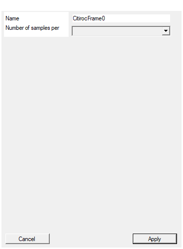
Set the name of the endpoint
Name of the memory-mapped FIFO endpoint, and the name embedded in every generated
symbol: the registers become SCI_REG_<name>_CONTROL / _STATUS /
_FIFOADDRESS, and the API functions become CitirocFRAME_<name>_START,
_RESET, _GetStatus, _DOWNLOAD, _RECONSTRUCT_DATA (plus _GET_STATUS and
_GET_DATA in Python). Changing it rebuilds the symbol.
Default: CitirocFrame0
Default: CitirocFrame0
Set the number of samples stored for each acquisition
Depth of the readout FIFO, in 32-bit words (not in samples per channel, despite
the caption). Passed to the memLength generic and used as the XPM
FIFO_WRITE_DEPTH. Capacity in events is Samples / 41.
| Value | Events buffered |
|---|---|
| 1024 | 24 |
| 4096 | 99 |
| 8192 | 199 |
| 16384 | 399 |
| 32768 | 799 |
| 65536 | 1598 |
| 131072 | 3196 |
| 262144 | 6393 |
Unlike the V1 block, all eight values are usable here: the FIFO word count sits
at bit 8 of STATUS instead of bit 16, so even an 18-bit count fits inside the
32-bit register.
Default: 8192
Default: 8192
Options: 1024 4096 8192 16384 32768 65536 131072 262144
⚙️ Detailed Operation
Packet layout — 41 words of 32 bits
Derived from CitirocFrameTransfer_NEW.vhd and from the channel-word packing in
CitirocAnalogReadout_NEW.vhd.
| Word | Content |
|---|---|
| 0 | 0x8000000n — sync header, n = ASIC index (A=0, B=1, C=2, D=3) |
| 1 | TS_T0_x — 32-bit run timestamp |
| 2 | TS_x[31:0] — event timestamp, low half (TDC-refined: low 4 bits are fine time) |
| 3 | TS_x[63:32] — event timestamp, high half |
| 4 | event counter of this block, free running |
| 5 | ASIC channel 31 data word |
| 6 | ASIC channel 30 data word |
| … | … |
| 36 | ASIC channel 0 data word |
| 37 | CNT_TRIGGER_x — trigger counter from the analog block |
| 38 | CNT_VAL_x — validation counter from the analog block |
| 39 | FLAGS_x — event status word |
| 40 | 0xC0000000 — trailer |
Each channel data word (identical to V1):
| Bits | Field | Width |
|---|---|---|
| 31:29 | reserved, always 000 |
3 |
| 28 | Hit — channel discriminator |
1 |
| 27:14 | ChargeLg — low-gain charge |
14 |
| 13:0 | ChargeHg — high-gain charge |
14 |
Word 39, FLAGS, as produced by the Citiroc Analog - TDC (V2) block:
| Value | Meaning |
|---|---|
0x00000000 |
Validation disabled — the event was read out unconditionally |
0x00000001 |
Validated in time |
0x00000002 |
Validation timeout |
0x00000003 |
Forced frame: a validation arrived with no event in flight |
A minimal correct decoder:
c
/* 41-word CitirocFrameTransferV2 packet */
#define CITIROC_V2_PACKET_WORDS 41
int decode_v2(const uint32_t *w, int n)
{
int i = 0;
while (i + CITIROC_V2_PACKET_WORDS <= n) {
if ((w[i] >> 4) != 0x8000000) { i++; continue; } /* hunt header */
if ((w[i + 40] & 0xC0000000) != 0xC0000000) { i++; continue; } /* trailer */
uint32_t asic_id = w[i + 0] & 0xF;
uint32_t time_code = w[i + 1];
uint64_t run_time = (uint64_t)w[i + 2] | ((uint64_t)w[i + 3] << 32);
uint32_t pack_id = w[i + 4];
uint32_t cnt_trig = w[i + 37];
uint32_t cnt_val = w[i + 38];
uint32_t flags = w[i + 39];
for (int k = 0; k < 32; k++) {
int ch = 31 - k; /* channel words arrive reversed */
uint32_t d = w[i + 5 + k];
uint32_t hg = d & 0x3FFF;
uint32_t lg = (d >> 14) & 0x3FFF;
uint32_t hit = (d >> 28) & 0x1;
/* ... store under channel `ch` ... */
}
i += CITIROC_V2_PACKET_WORDS;
}
return i;
}
Round-robin arbiter and event loss
Unchanged from V1: the poll slot advances every clock through A, B, C, D, so a DV_x is
serviced within at most four cycles; the whole event is latched in one cycle; BUSY
covers the 41 write cycles.
FIFO thresholds
With memLength = Samples and MaxPacketSize = 38 * 2 = 76:
| XPM parameter | Value | Effect |
|---|---|---|
FIFO_WRITE_DEPTH |
Samples |
total depth in 32-bit words |
PROG_FULL_THRESH |
Samples − 76 |
drives FULL / FIFO_FULL — two packets of headroom |
PROG_EMPTY_THRESH |
76 |
drives DATA_AVAL and STATUS[0] |
READ_MODE |
"std", latency 1 |
standard (non-FWFT) read |
The doubled threshold means DATA_AVAL only rises when at least two complete
41-word packets are buffered, and FULL warns two packets early instead of one.
Capacity in events is Samples / 41: 199 packets at the default 8192.
Control and status registers
CompileMMC declares one FIFO-read endpoint named after EndpointName, with two
auto-registers — same map as V1.
CONTROL (write)
| Bit | Function |
|---|---|
| 0 | Mask ASIC A — 1 = ignore DV_A |
| 1 | Mask ASIC B |
| 2 | Mask ASIC C |
| 3 | Mask ASIC D |
| 8 | Reset / flush — holds the arbiter and FIFO in reset, clears the event counter |
STATUS (read)
| Bits | Function |
|---|---|
| 0 | Data available (1 = at least two packets buffered) |
8 + rBits − 1 : 8 |
Words currently in the FIFO, rBits = ceil(log2(Samples)) |
Generated software API
Identical names and bodies to the V1 block:
| Function | What it does |
|---|---|
CitirocFRAME_<name>_START(handle) |
writes 0 to CONTROL — releases the reset, unmasks all four ASICs |
CitirocFRAME_<name>_RESET(handle) |
writes 0x100 to CONTROL — asserts the flush and holds it |
CitirocFRAME_<name>_GetStatus(&is_data_available, &word_available, handle) |
reads STATUS (see the alert above about word_available) |
CitirocFRAME_<name>_DOWNLOAD(val, size, timeout, handle, &read_data, &valid_data) |
bulk FIFO read; val must be preallocated to size + 16 words |
CitirocFRAME_<name>_RECONSTRUCT_DATA(buffer_handle, &decoded_packets) |
the V1 38-word decoder — see the alert above |
A RESET only asserts the flush; always follow it with a START.
When sizing a download, use 41 words per packet, not the 37 or 38 the shipped examples use:
c
CitirocFRAME_CitirocFrame0_DOWNLOAD(data_frame, N_Packet * 41, 1000,
&handle, &read_data_frame, &valid_data_frame);
Differences from Citiroc Frame Transfer (V1) at a glance
| V1 | V2 (this block) | |
|---|---|---|
HDL written to pcores/ |
CitirocFrameTransfer.vhd (from CitirocFrameTransfer.vhd) |
CitirocFrameTransferV2.vhd (from CitirocFrameTransfer_NEW.vhd) |
| Packet size | 38 words | 41 words |
| Extra payload | — | CNT_TRIGGER, CNT_VAL, FLAGS before the trailer |
| Extra input pins | — | CNT_TRIGGER_x, CNT_VAL_x, FLAGS_x (×4) and CFG |
MaxPacketSize (FIFO thresholds) |
38 | 76 |
FIFO word count in STATUS |
bits 16 + | bits 8 + |
Samples = 131072 / 262144 |
unusable (status slice overflows) | usable |
BUSY value while in reset |
0 |
1 |
| Generated decoder | matches | still the 38-word V1 decoder |
Note also that BUSY resets to 1 in this version (V1 resets it to 0), so the block
reports busy while FLUSH or CONTROL[8] is held.
Typical wiring
Citiroc Analog - TDC (A) ─DATA_A/TS_A/TS_T0_A/DV_A──────────►┌──────────────────┐
─CNT_TRIGGER_A/CNT_VAL_A/FLAGS_A───►│ │
◄──────────────── ACK_A ────────────│ Citiroc Frame │──► FIFO endpoint ──► PC
Citiroc Analog - TDC (B) ──────────────────────────────────►│ Transfer (V2) │
Citiroc Analog - TDC (C) ──────────────────────────────────►│ │──► FULL / DATA_AVAL / BUSY
Citiroc Analog - TDC (D) ──────────────────────────────────►└──────────────────┘
FLUSH ───────►
Resources & Timing
-
Latency: Up to 4 clock cycles from
DV_xtoACK_x(round-robin poll), then 41 clock cycles to write the packet into the FIFO -
Throughput: One 41-word packet per 41 write clocks, shared by the four ASICs
- Emits
pcores/CitirocFrameTransferV2.vhd(entityCitirocFrameTransferV2) from theCitirocFrameTransfer_NEW.vhdresource. - One event = 41 words = 164 bytes on the wire.
xpm_fifo_asyncwith independent write (CLK) and read (READ_CLK) clocks; the compiler currently binds both to the project global clock.- The generated C/Python decoder is the V1 38-word one and will not decode this block’s packets — see the alert in the description.
- Supported board: DT5550W-Citiroc1A-V2 (
26E86B08-6FEF-4B0F-8872-793CC478DA97). Not available inside subpages or state machines.