
Counter Rising Edge (Async)
Asynchronous edge counter that counts rising edges on an input signal. Counter increments directly on input edges without clock synchronization, enabling counting of frequencies higher than system clock. Features gated counting control and overflow detection. Configurable counter width from 8 to 64 bits.
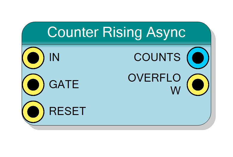
Introduction
This block counts rising edges asynchronously - the IN signal directly clocks the counter without synchronization to the system clock. This enables counting frequencies higher than the system clock frequency.
Key features:
- Counts rising edges asynchronously (no clock frequency limit)
- Can count signals faster than system clock
- Optional gating control via GATE input
- Overflow detection
- Configurable counter width (8-64 bits)
Key difference from synchronous counter:
- Synchronous: Max input freq = CLK_Freq / 2
- Asynchronous: Max input freq » CLK_Freq (limited only by FPGA timing)
$$ \mathrm{COUNTS}(n+1) = \mathrm{COUNTS}(n) + 1 \quad \text{on each Rising Edge of IN} $$
Pin Description
Input signal to count (asynchronous clock).
Rising edges directly increment the counter without synchronization.
Frequency capability:
- No theoretical upper limit from system clock
- Practical limit: ~500 MHz (FPGA dependent)
- Far exceeds synchronous counter (CLK_Freq/2 limit)
Signal requirements:
- Clean edges (no bouncing/glitches)
- Minimum pulse width: ~2-3 ns (FPGA Tsu+Th)
- Duty cycle: No specific requirement
Edge type: Rising edge (0→1 transition) increments counter
Warning: This signal operates in a different clock domain than the system clock. Reading COUNTS requires care to avoid metastability.
Gate control input (active high).
- ‘1’ = Counting enabled
- ‘0’ = Counting disabled (counter holds value)
Important: GATE should be static or carefully synchronized to avoid metastability. Changing GATE during IN transitions may cause glitches.
Best practice: Change GATE only when IN is stable.
Default: Connects to ‘1’ if left unconnected.
Asynchronous reset input (active high).
- ‘1’ = Reset counter to 0 immediately
- ‘0’ = Normal operation
Asynchronous reset: Takes effect immediately, not synchronized to any clock.
Important: Assert RESET for at least several ns to ensure all counter stages reset.
Default: Connects to global reset if left unconnected.
Current count output (unsigned integer).
Contains number of rising edges detected since last reset.
Width: Configured by Bit Number property
Behavior:
- Increments asynchronously on each IN rising edge
- Changes not synchronized to system clock
- Wraps to 0 after maximum (2^BitNumber - 1)
CRITICAL - Reading this output: This output is in the IN clock domain, NOT system clock domain.
Safe reading methods:
- Double-synchronize: Pass through 2 flip-flops clocked by system clock (adds 2 cycle latency)
- Gray code: Convert to gray before synchronizing
- Static read: Only read when IN is guaranteed static
- Accept metastability: In applications where occasional glitches are acceptable
Metastability risk: Reading during counter update can capture inconsistent multi-bit value.
Output type: Combinational/asynchronous (not registered to CLK)
Overflow flag output (pulse).
Pulses when counter wraps from maximum (2^BitNumber - 1) to 0.
Timing: Pulse is asynchronous, occurs on IN edge that causes wrap.
Synchronization: Like COUNTS, this is in IN clock domain. Should be synchronized to system clock if used in synchronous logic.
Use cases:
- Extended precision counting (cascade counters)
- Overflow detection
- Frequency division (pulse every 2^N input edges)
Output type: Asynchronous (not synchronized to CLK)
Properties
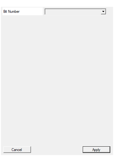
Set the number of bit used in the counter accumulator
Number of bits in the counter.
Available values: 8, 16, 24, 32, 40, 48, 56, 64
Determines:
- Maximum count = 2^BitNumber - 1
- Overflow period = 2^BitNumber input edges
- Width of COUNTS output
Choose based on:
- Maximum expected count between resets/reads
- Acceptable overflow rate
- Precision requirements
Note: Wider counters (32+ bits) have longer ripple delay through counter stages. For very high frequencies (>200 MHz), consider using prescaler followed by narrower counter.
Default: 32
Options: 8 16 24 32 40 48 56 64
Functional description
The asynchronous counter uses the IN signal directly as clock for the counter:
Asynchronous operation
Unlike synchronous counters that sample input on system clock:
- Rising edge on IN directly increments counter
- No system clock synchronization
- No sampling or edge detection logic
- Immediate response to input edges
Advantages of asynchronous counting
Higher frequency capability:
- Not limited by system clock frequency
- Can count GHz signals with MHz system clock
- Only limited by FPGA flip-flop toggle rate (~500 MHz typical)
Lower latency:
- Zero clock cycle latency
- Immediate count update on input edge
Disadvantages of asynchronous counting
Metastability risk:
- COUNTS output can have intermediate values when read
- Reading during counter update can capture inconsistent state
- Requires careful read timing or gray code conversion
Limited gating:
- GATE control has constraints
- May not be glitch-immune like synchronous version
Timing complexity:
- Counter in different clock domain than system
- Requires careful timing analysis
- Clock domain crossing considerations
Comparison: Synchronous vs Asynchronous
| Feature | Synchronous Counter | Asynchronous Counter |
|---|---|---|
| Max input frequency | CLK_Freq / 2 | ~500 MHz (FPGA limit) |
| Clock dependency | System clock | Input signal |
| Metastability risk | None | Yes (when reading) |
| Read timing | Any time (stable) | Careful timing needed |
| Glitch immunity | Excellent | Limited |
| Latency | 1-2 cycles | ~0 cycles |
| Best for | <50 MHz, clean reads | >50 MHz, async signals |
Timing considerations
Reading the counter safely
Problem: Counter bits may change at different times (ripple effect)
Solutions:
- Sample during known-stable period (when IN is static)
- Use gray code converter (only one bit changes per count)
- Double-register in system clock domain
- Gate input during read (freeze counter)
Example safe read timing
- IN runs faster than CLK
- COUNTS increments on each IN edge
- System samples COUNTS on slow CLK
- Some counts may be missed, but values are monotonic
Typical use cases
- High-frequency counting: Count RF signals, fast clocks (>100 MHz)
- External clock counting: Count pulses from external high-speed source
- Totalizing counter: Accumulate pulses regardless of system clock
- Prescaler input: Count down high-frequency signals before processing
- Event logging: Count rapid asynchronous events
- Encoder counting: High-speed motor encoder inputs
Design considerations
When to use Asynchronous counter
Use Asynchronous if:
- Input frequency > System clock / 2
- Input is asynchronous to system
- Need maximum frequency capability
- Can tolerate metastability (with proper handling)
Use Synchronous if:
- Input frequency < System clock / 4
- Need glitch-free, stable reads
- Integration with synchronous logic
- Avoiding metastability is critical
Metastability mitigation
When reading asynchronous counter:
-
Double synchronizer:
COUNTS → FF1 → FF2 → COUNTS_safe (system clock domain)Adds 2 clock cycle latency, reduces metastability risk
-
Gray code: Convert counter to gray code (only 1 bit changes per count) Synchronize gray code, convert back to binary
-
Handshake protocol: Request count → Freeze counter → Read → Release
Input signal quality
- Clean edges required (no bouncing)
- Minimum pulse width: FPGA Tsu + Th (~2-3 ns)
- Maximum frequency: ~500 MHz (FPGA dependent)
- Glitches will be counted as edges
GATE control limitations
- GATE signal should be static or synchronized
- Avoid changing GATE during IN transitions
- GATE metastability possible if asynchronous to IN
Resource usage
- Similar to synchronous counter
- May use less logic (no edge detection)
- Same number of flip-flops