
Polarity Invert
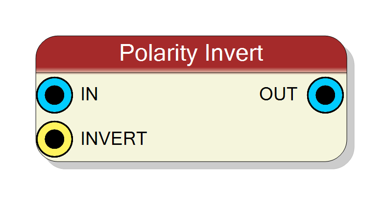
Switchable polarity inverter for a single data stream. A one-bit control pin chooses between pass-through and inversion; the inversion itself is a reflection about full scale in UNSIGNED mode and a two’s-complement negation in SIGNED mode. Purely combinational, zero latency, and it operates on the lowest Effective # bits of the word.
Introduction
Principle of Operation
Detectors and preamplifiers come in both polarities, and most downstream
processing (trapezoidal shapers, peak detectors, discriminators) expects
positive-going pulses. Polarity Invert makes that a runtime choice: raise
INVERT and the stream is flipped, lower it and the stream passes through
untouched.
What “flipped” means depends on the Input sign property, and the two answers are genuinely different operations — not two spellings of the same one:
| Input sign | operation when INVERT = 1 |
in words |
|---|---|---|
UNSIGNED |
$y = (2^{N_{\rm eff}} - 1) - x$ | reflection about full scale — this is the bitwise complement, $y = \overline{x}$ |
SIGNED |
$y = -x \pmod{2^{N_{\rm eff}}}$ | two’s-complement negation |
$N_{\rm eff}$ is the Effective # bits property, not the port width. Both paths are pure combinational logic: the output changes in the same clock period as the input, with zero latency and no clock or reset pin.
Which mode do I want?
UNSIGNEDis the natural choice for a raw ADC stream. A negative-going pulse sitting on a pedestal near full scale becomes a positive-going pulse sitting on a pedestal near zero, and the pedestal moves with it — the baseline restorer downstream will absorb the shift. Nothing can overflow, because the mapping $x \mapsto \overline{x}$ is a bijection of the $N_{\rm eff}$-bit range onto itself.SIGNEDis the choice once the pedestal has already been removed and the stream is a signed excursion about zero. It is a true negation, so it preserves the “distance from zero” of every sample — at the price of the one edge case described below.
Pin Description
IN on the canvas), Input bits wide. Only the low
Effective # bits are used; anything above them is discarded, inverted or
not.
Invert control (INVERT on the canvas), one bit, sampled
combinationally.
- 0 → output = input (truncated to Effective # bits)
- 1 → output = inverted input, per Input sign
It has no default: drive it from a register or a constant.
OUT on the canvas), same width as the input. Valid in
the same clock period as IN — there is no pipeline register. Note the
zero-extension caveat when Effective # bits < Input bits in SIGNED
mode.
Properties
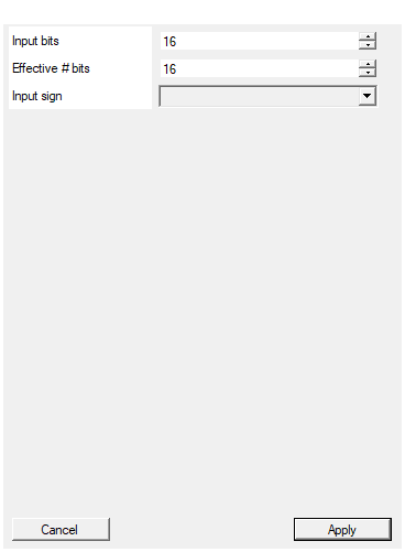
Set the number of bits of the input
Width in bits of IN and OUT — they always match. This is the width of
the bus, not the resolution of the data; use Effective # bits for that.
Range: 2 to 2048. Changing it rebuilds the symbol.
Default: 16
Default: 16
Range: 2 – 2048
Set the effective number of significative bits in the data. For example for 14 bit ADC board set this number to 14
Effective # bits — the number of significant bits actually carried in the
low end of the word, and the width the inversion is computed in. On a
14-bit ADC carried in a 16-bit bus, set it to 14: the UNSIGNED
reflection then mirrors about $2^{14}-1$ instead of $2^{16}-1$.
Must be less than or equal to Input bits: the core slices
a(EffSize-1 downto 0), so a larger value is an out-of-range slice and the
design will not elaborate. Bits above it are discarded.
Range: 2 to 2048.
Default: 16
Default: 16
Range: 2 – 2048
Select the sign/unsign of the input
How the word is interpreted, and therefore what “invert” means.
| value | inversion | overflow behaviour |
|---|---|---|
UNSIGNED |
$y = (2^{N_{\rm eff}}-1) - x$, i.e. bitwise NOT | cannot overflow |
SIGNED |
$y = -x$ in two’s complement | $-2^{N_{\rm eff}-1}$ wraps onto itself; no saturation |
Fixed at synthesis (it becomes the SIGN generic) — it cannot be switched
at runtime, only INVERT can.
Default: UNSIGNED
Default: UNSIGNED
Options: UNSIGNED SIGNED
⚙️ Detailed Operation
Datapath
The core (Resources/Code/polinvert.vhd) is three concurrent statements:
A_SIZE bits AN_SIZE bits A_SIZE bits
IN ───►[ take the low AN_SIZE bits ]───► aa ───►[ invert ]───► bb ───►[ resize ]───► OUT
▲
INVERT ────┘
with the generics driven from the properties: A_SIZE = Input bits,
AN_SIZE = Effective # bits, SIGN = Input sign.
INVERT= 0 →bb = aa, a straight copy.INVERT= 1,SIGN = "UNSIGNED"→bb = A_MAX - aa, whereA_MAXisAN_SIZEones, i.e. $2^{N_{\rm eff}}-1$. Subtracting from an all-ones constant never borrows, so this is exactly the bitwise NOT of the word.INVERT= 1,SIGN = "SIGNED"→bb = 0 - aa, evaluated inAN_SIZE-bit signed arithmetic.
The one thing people get wrong: the most negative value
In SIGNED mode the subtraction is performed modulo $2^{N_{\rm eff}}$ and is
never clamped. The architecture does declare an A_MIN/A_MAX pair in the
signed branch, but nothing ever reads them — there is no saturation logic
anywhere in the file.
So for the most negative representable sample:
$$ -2^{N_{\rm eff}-1} ;\longmapsto; 0 - \left(-2^{N_{\rm eff}-1}\right) = 2^{N_{\rm eff}-1} \equiv -2^{N_{\rm eff}-1} $$
With Effective # bits = 16, input 0x8000 (−32768) comes out as 0x8000
(−32768) — the sample is not inverted, it wraps back onto itself. Every
other value negates correctly.
Effective # bits = 8, SIGNED, INVERT = 1 |
||
|---|---|---|
| IN | OUT | note |
0x00 (0) |
0x00 (0) |
|
0x01 (1) |
0xFF (−1) |
|
0x7F (127) |
0x81 (−127) |
|
0x80 (−128) |
0x80 (−128) |
wraps — not saturated to +127 |
Effective # bits truncates, in both directions
aa is taken as the low AN_SIZE bits of the input, and the result is
resized back to A_SIZE. That has two consequences that hold even when
INVERT = 0:
- Any input bit above Effective # bits is discarded. The block is not a transparent pass-through when Effective # bits < Input bits.
- The reflection point in
UNSIGNEDmode is $2^{N_{\rm eff}}-1$, not $2^{N_{\rm in}}-1$. This is the whole purpose of the property: on a board whose 14-bit ADC is carried in a 16-bit bus, set Effective # bits = 14 and the inversion mirrors about 16383, which is what the detector actually sees. Leave it at 16 and the pulses will be mirrored about 65535 and end up 49152 counts away from where you wanted them.
Configuration
Neither the size nor the sign can be changed at runtime: Input bits,
Effective # bits and Input sign become VHDL generics and are fixed at
synthesis. Only INVERT is a live control. The usual pattern is to drive
INVERT from a Register block so the SciSDK can flip the polarity per
detector without rebuilding the firmware:
ADC ──────────────► IN ┌─────────────┐
│ Polarity │──► OUT ──► shaper / trigger chain
Register (1 bit) ─► INVERT Invert │
└─────────────┘
INVERT is a plain one-bit input with no defined default in the component, so
wire it explicitly — to a register, or to a constant if the polarity is fixed
in your design.
Timing
| quantity | value |
|---|---|
| latency | 0 clocks (combinational) |
| throughput | one sample per clock of the surrounding logic |
| clock / reset | none — the block has no sequential elements |
Because it is combinational, the inverter sits inside the timing path of whatever drives and consumes it; at high clock rates on a wide bus, place a register block after it if timing closure becomes tight.
Resources & Timing
-
Latency: 0 clocks — purely combinational, no clock or reset pin
-
Throughput: 1 sample per clock of the surrounding pipeline
- Cost is one Effective # bits-wide subtractor plus a multiplexer; in
UNSIGNEDmode the subtractor degenerates to an XOR with all-ones, which synthesis reduces to inverters. - No memory-mapped registers are generated.
- The
INVERTpin is shared logic for the whole word; use the TM twin, Polarity Invert (TM), for time-multiplexed buses.